There’s a whole slew of ways of heating up the printer. People have heated their rooms (expensive). Put the resin printer on a heated printer bed! (genius, and works). They’ve also cobbled together a bunch ‘o bits and made a heater. Probably the most elegant one i’ve seen is by Elegoo!
I worry that the commercial ones may be too powerful I only need to raise the temperature around 10-15 degrees above ambient. Having seen friends use 50watt lamps in vivariums of much larger volume than my printers, I’ve figured a 50 Watt dedicated heater device should be more than enough….
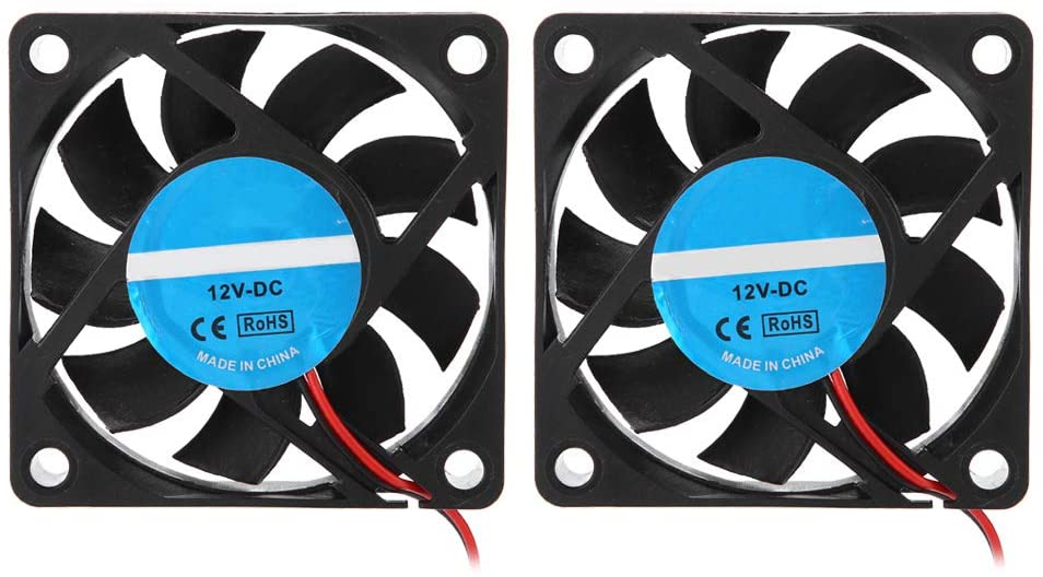
Thank ME for this one – I purchased 5 off 80mm Artic F8 case fans back in March last year for an absolute steal. With the intention of upgrading cooling on the Wanhao D9 and in anticipation of designing a small heater for the resin printers. I can’t find them, so, this pair was about the best deal I could find for quick delivery
This lot cost me about £20 in total – Not bad considering it’ll be twice as ugly as the £10 commercial units, which, at £10 will be delivered in March, which co-incidentally is about the same date that i’ll likley finish assembling this monstosity!, D’oh!
ah well……..
Now, All I need to do is create some sort of 3D printed enclosure to house ’em all, figure out how to route cables and voila, i’ll have a nice ‘thingy’
Note, this lot can be gotten for easily around a tenner total, if your patient. However, It’s cold NOW, so i can’t wait a few months for delivery (when, in the UK it’ll still be cold, just a bit less cold)
Very early days yet on this design. A couple of hours of measuring and sketching in Fusion360. Needs some finessing, but the principle is sound.
Given 90% of my printed things are quite short, (keyboards, Mini computer case prototypes and miniature monsters) I can comfortably make a very efficient 90 Degree bed resin drip drainer and keep the cover on!
Most drainers are maybe 20-40 degrees or so!
The new Drainer bracket in Yellow – Sits permanently on the printerAnd, the position of the bed when it’s rotated 90 Degrees. The Yellow bracket and the original ‘stick out bed holder’ clamp the bed sideways between then! The ‘curve’ bit stops the bed sliding too much to the right and ‘off’.
Having some fun with the printer this past few weeks. many, many fails
Lightly used, honest
Some possible lessons learned….
1 – Don’t mix Resin brands and pigments in untested combinations
I’d ordered a bunch of ‘expired’ Elegoo translucent green resin, going ridiculously cheap, (like 1/3rd the price it should be) it prints FANTASTICALLY…BUT
….I normally use Anycubic Clear, just because it’s what i started with, and it works.
Mixing in an old batch of C64 Brown with the new Elegoo didn’t really work. I had 6 failures in a row – which i’d assumed was the FEP or me doing something silly / bad levelling . The 7th failure punctured the FEP! At that point i’d realised what i’d done (mixing all the stuff together) so, ordered some new Clear resin. I got a perfect print straight away!
The thing you see above is me, changing the supports (finally) after having issues with the old base layer being too thick and seperating from the build plate. I’d gotten around this by using longer base exposures, but still, had more failures than I’d like.
Hopefully now i’ve new FEP, new resin, and spent a couple of hours doing the supports properly, I’ll get a fresh print tomorrow!
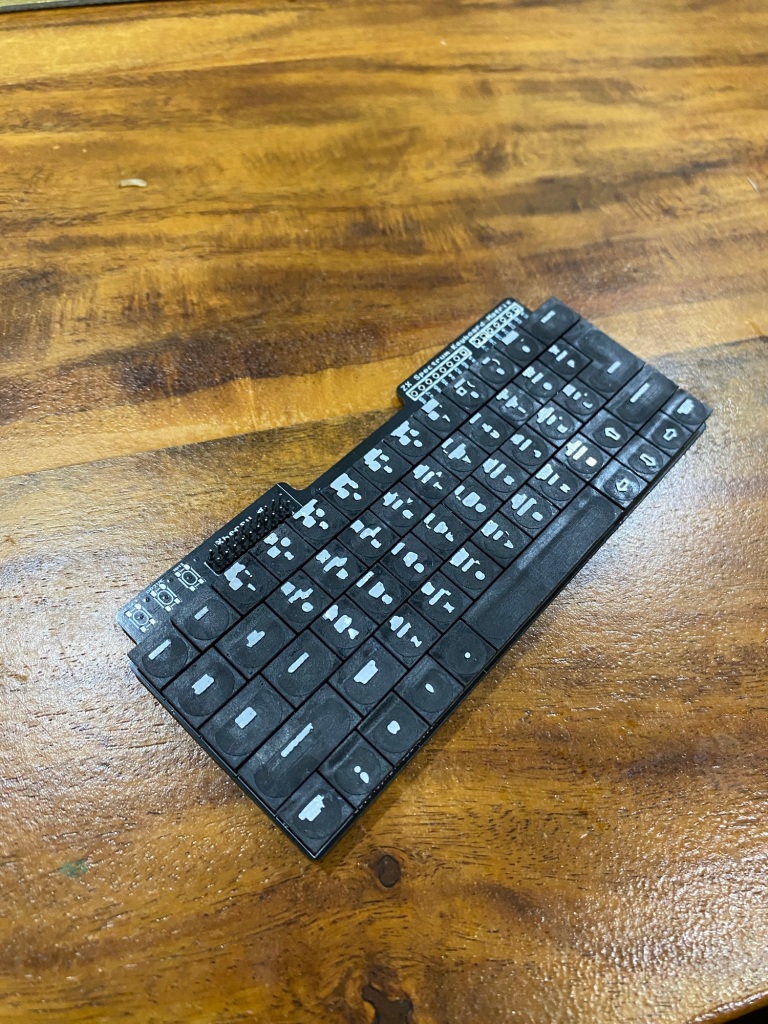
anyone good with QMK?
My next issue – as you can see above…QMK. I spent weeks learning how to, and setting up QMK on my old laptop, which the kids smashed.
QMK has moved on a little it seems as now there’s a dedicated QMK MSYS32 installation…BUT, it doesn’t compile my old keyboard layout. if there’s anyone good with QMK out there, give me a shout!. I’ve no doubt I can get things working again to work on the code a little, just pressed for time for the next month or two and, i’m getting the coding itch this past few days 😛
Who knows if it’ll work yet, but whilst trying to support a large, flat, thin surface for printing, I found that the slicing software didn’t really seem to ‘get it’
So, I tricked it a little by adding the seeds for supports inside Fusion360
Essentially this is just creating a grid of ‘support tips’ and merging them with the wanted body.
The slicer software sees these tiny sticky-outy bits and has no choice other than to add supports to them
alternatley, they can serve as a grid for you to add some manual ‘heavy duty’ supports and surround with more medium duty ones
This is a large flat lower part of a case.
Angle it by 45 degrees. This makes it short enough to print, and easy to support and add some ‘zits’ on a grid
Closeup of zits on a grid
By adding an easy ‘pattern’ of 0.5mm high by 0.1mm diameter zits, I trick Lychee into supporting those areas.
The End result – Evenly spaced ‘starter’ supports that can be manually supplemented. This ensures that no points of the model will be droopy.
I’ve started with a grid around 10x10mm. no reason why this grid can’t be a bit smaller, just some experimenting needed
Arduino’s are still stuck in Limbo. I received 50 incorrect ones a long while back, ordered another 50 and they’ve been stuck somewhere in the UK for a couple of weeks now. I did order 10 locally at about 2x the price I normally pay to work through some of the waiting list, but that exhaused my supply of PCB’s
So, I ordered back at the beginning of February some more PCB’s
They arrived yesterday, and, I quickly soldered one up to test, so I can start ‘kitting up’ the keyboard kits.
I may have discovered an issue with the way that i’m Using EASYEDA, which has recently shown up in an EASYEDA update….it could be a bug, or a behaviour change, but, it’s B0rked my PCB!
This will set back the kit availability a couple of weeks whilst I address it and get new boards made. I know what the issue is, I can re-create it and have a work around to order more PCB’s so it’s no major worry
Here’s the C64 Keybaord matrix that i’m using. I’ve always used number prefixes for the number keys. i.e. if it’s A, I’ve used the PREFIX A, 1, Prefix 1, etc , etc.
Something changed in EASYEDA a couple of months ago which now means that Prefixes with a single digit number now all seem to tie their nets together.
Here’s the resulting PCB – Note, the nets for the centre pins are all the same!
I didn’t spot this in the one that I just had made! and despite the thoroughly heroic efforts of the JLCPCB staff to fix a couple of cockups i’d made , I have to now trash this batch .
Here’s what happens when I select the Net – ALL the numbers light up as they’re all connected!. oops
Ah well, off to learn a little more about EASYEDA, quite an expensive mistake though, but this shows why, when you make changes, testing is important.
You can imagine how amused I was when I discovered that EVERY key worked on my board, except the number keys, which only typed 0 or 9 !
In other news – I purchased one of these
An Ultrasonic Cleaner – Dual Frequency 28KHz and 40KHz. I’ll do another post about it later.
All i can say now is WOW – No need for the wash and cure station now! – this thing superbly and consistently cleans the prints, giving a good surface finish. Prior to this, it was impossible to get a good finish on every key, every time. Now, i’m 4 prints in , and 3 are perfect, 1 is crap due to over-cleaning! I’m dialled in and ready for production
Whilst developing the Commodore 64 mini keycaps and iterating the prints, it came clear that the caps are little buckets that hold quite a lot of resin.
I’ve been holding the keyboard over the tray to drain all this resin out, and it takes “ages”
So, when you can use CAD and have a few 3D printers , you go and spend time developing a widget to optimise the amount of time holding a build plate at an angle!
And by “spend time”, and “optimise”, I mean, take longer doing in CAD than the total amount of time that would have been spent holding the bed in the first place
I present….
60 degrees! version 1
Total amount of time in CAD, and reworking, maybe 3 hours…
Total amount of time holding a bed to drain, maybe 3 minutes.
Number of beds to hold to recoup time in CAD…60!
So, after 60 prints, I’ll have broken even on the time invested in making the thing!
Here it is in action!
Version 1 wasn’t as optimal, it needed shifting over to the left by about 30mm to give far more clearance on the case for everyone not printing 25mm high keycaps to be able to use.
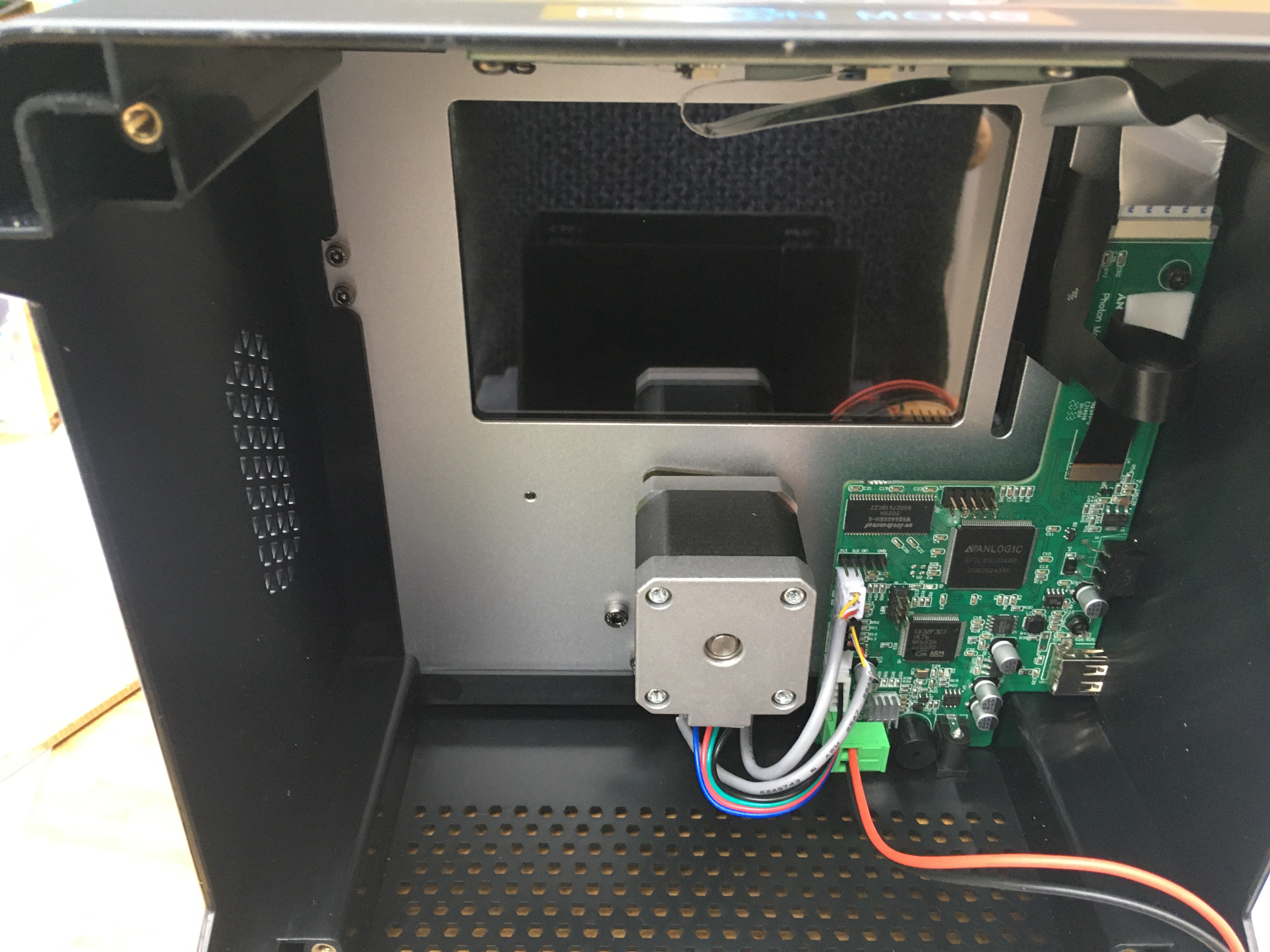
1- The Anycubic Photon Mono board is possibly capable of using a 4K LCD
also, i’ve spotted that Chitu systems sells an ESP8266 module specifically for their boards – it could be that Anycubic plans on selling their own, or just goofed up with the polarity of the header on the board!
And, finally, after all the above, that i’m going to publish anyway, i’ve also spotted
The Wanhao printer bed is made of Aluminium, below this is a flexible heating element.
It’s been widely reported that the D9 doesn’t level very easilly, Here’s why people are having issues….
Aluminium expands when heated!
If you’re having ‘levelling issues’ ensure to do the electronic bed levelling whilst the bed is hot! – (pre-heat to typical printing temperature first)
Density – Steel (which the carriage is made of) is generally around the 7 – 8 g/cm³ – or Three times that of Aluminium! – win there, I can use a sheet of aluminium Three times thicker than the steel on the carriage and have the same weight (in theory)
Thermal Expansion – Translated this means that Aluminium expands by 24 micrometers per millikelvin. Also known as 0.000024 meters per degree
How does this affect the D9 Printbed?
When heated, the 325 x 325 x 2mm thick aluminium bed becomes a bit larger
The Cheapy ‘Hiwin’ clone rails and blocks arrived a while back and they haven’t really dissapointed. By that, I mean, I kinda got what I was expecting. Still, only a small premium paid and 3 workable carriages / rails……
Iteration……it’s all about trying, adjusting, trying again. from the first basic drawing on the left and the first print….right through to the Rev6 print (that’s now REV 7)
The tall bit pushes against the conservatory roof…the little ‘hook’ holds it in place on a small ledge, the long dangly bit presses against the wall and holds the LED strip….REV 7 increases the length of the sticky uppy bit on the right!
Also purchased a few types of incredibly sticky double sided stuff….they just would not stick……The sticky pads stuck to the PVC windows just fine, but whatever teflon type material the clear IP tubes are made of, well, it’s better than teflon, nowt’ll hold that up….
Enter my shiny new 3D printer….A few brackets will hold them up nicely!
I used some Playdoh to get an idea of the outline of the PVC Ledge that I could clip some holders to…Made some drawings and knocked up something in Tinkercad
On the left is my first foray into 3D cad in nearly two decades….I’ve merged them to show the Rev7 bracket that i’m now to print….
I’m amazed really, in modern times, a 3D printer enables you to take some measurements….Create an item, try for fit….re-design the item, try again…..rinse, repeat….in just a few hours!. 7 iterations of trying, wiggling about an ‘guessing’ what needed changing and it’s done (till I improve and get to rev 10 :-P)
I’ve a long print running, but when it finishes, i’ll print up about 20 of these in clear filament and show the final product installed….can’t wait!
There’s LOADS of videos, methods ,etc out there….this way is SIMPLE, CONSISTENT and reliable
Make sure your printer head is clean and free from cooled plastic
MAKE SURE THE BED IS CLEAN...(I’m using baby wet wipes, but they dont’ seem to be the best, i’ll need to try isopropyl alcohol like the old timers are)
How to clean….Use a sponge, soap and water………that’s it!
1 – LEVEL the Z axis – use a ruler / visual marks on the back, whatever, make sure the bar is level
2 – Use the menu to go into the LEVEL selection
3 – Get the Z axis offset correct by using a piece of paper so it’s just gripped by the head
4 – TURN OFF THE PRINTER (yes, TURN IT OFF, DO NOT CLICK NEXT)
5 – MANUALLY move the print head to CLOSE (maybe 10mm away from) to the corners…
Start on one corner – use the paper between the head and the bed…adjust the screw in that corner till it just grips.
Move to the next corner, repeat
repeat again
repeat again
6 – Go back and check each corner and tweak slightly if necessary
7 – Turn printer on and LEVEL THE BED IN SOFTWARE AS NORMAL……
Now, if you really want to be pedantic, you should do this whilst everything’s warmed up to your normal working temperatures!
After figuring out that 20mm, just ain’t good enough to calibrate, I had a nose around on thingverse….
The largest ‘calibration’ thing I found was the above 280 x 280mm square……..Awesome, that’s good enough, close to 300mm too for maximum calibratory goodness…
Lots of basic printing suggested that the front to back measurement was slightly off…so, finally I’ve decided to calibrate the printer….
By, printing a calibration cube! I’ll do it a little differently and record just a bit more information…I’ll measure 3 points for each axis, giving 9 points for the cube….
I get no benefits at all by linking to these guys, just highlighting a superb printer (so far!) for a superb price here in the UK
Immediate upgrades – Better wheels x 6 for the Y axis Bed (open builds type, see my other posts) and a better blower fan – <£40 extra and it’s a superb, 24V printer
Hmm, Looking at DWIN.COM.CN…There’s quite a few LCD’s that may fit the bill- quickly copy / pasted the parts into Excel – All are 2Gig memory and 4.3″ screens


 Finally –


