Copycats! – upcycling ikea tables for enclosure

Having two kids really means that you get almost Zero time to tinker, I can ponder many ideas, but often can’t carry them out in a reasonable time

Referring back to my post here – https://bleughbleugh.wordpress.com/2015/06/22/where-to-put-the-mill/

I’ve just googled someone that’s done just that!….

Sean's Ikea Lack Tables Enclosure
Sean’s Ikea Lack Tables Enclosure

http://3dprint.com/84409/ikea-3d-printer-enclosure/

Off to watch Mach 3 tutorial videos, mayaswell get some theory practice in!

It’s Alive, ALL 4 axis…..

It’s been a few weeks now, still haven’t actually cut anything proper like,

however, a BIG occasion, I can now JOG all 4 axis quite happily in Mach3!

for those looking everywhere (and I did), no-where really quite states obviously or easily the pins on the connector needed to control the 4th Axis, it’s pins 8 & 9

Axis Step Pin# Dir Pin#
X Axis 2 3
Y Axis 4 5
Z Axis 6 7
A Axis 8 9

And Also – another setting needed,

Under CONFIG – Homing / Limits.

Set Soft MAX and Soft MIN on A axis to ZERO, that’ll allow it to rotate forever.

Now, one plus side of getting the A axis to work, it uses the same stepper motors as the X,Y,Z. it should help me to be able to accuratley calibrate the system now as many websites suggest that the 400 steps per rotation is ‘off a bit’….

Here goes. Need to figure out ‘homing’ and how exactly the G-Code relates to the position on the table. most ‘dry runs’ so far have pushed the CNC past its limits…..which is annoying as i don’t have limit switches yet!

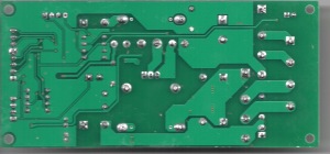
JP-1482 Spindle Board

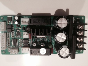
Noting some of the ‘stuff’ on the board, we can see that it’s quite simple really, it’s a small microprocessor controlled, dual sided PCB Two voltages – 18V AC and 36V AC from the secondaries of the transformers, 18V dropped down to 5V to feed the processor electrics….. 36V rectified to DC, then passed to the spindle somehow the micro takes in the variable resistance from the POT at the front of the box and converts it to DC, PWM at whatever voltage the 36V AC is converted down to. Not sure what the extra plugs do yet though, i’ll keep adding to this board STC 15W408AS –

  • SOP16 – Single Chip Micro – 8051 based – 8-12 times faster than standard 8051
  • 8K RAM,
  • 512 Bytes SRAM,
  • 3 Channel PWM,
  • 10 Bit ADC,
  • 5K EEPROM
  • UART
  • SPI
  • 5 external interrupts
  • 2 timers
  • comparator
  • internal clock
  • encryption
  • RS485 Control

Page 68 onwards of the english PDF datasheet covers this IC, LNK 306DN –  AC TO DC CONVERTOR – DATASHEET HERE – 8 PIN IC WITH PIN 3 MISSING IRF 640N – IOR P447D – 5TH Generation power Hexfet MOSFET – DATASHEET HERE KBJ 1510 – Bridge Rectifiers – DATA SHEET HERE 78M05  – 5V Voltage regulator – DATASHEET HERE EL817 X 4 4 PIN DIP PHOTOCOUPLER – AKA OPTOISOLATOR – DATASHEETS HERE ES1J X 3 – 1A Ultra fast recovery rectidier – DATASHEET HERE

Spindle Board
Spindle Board
Spindle Board - Top
Spindle Board – Top

There is a few versions of this board around, one older one seems similarly laid out but based upon a 555 timer! Theres a fellow Aussie doing much more digging than I at this time, ill pinch some wording from his page on how my board works. The spindle speed control works by passing the PWM through a low pass filter, then reading the DC voltage produced on an analog pin of a PIC micro. The micro then reads the value (most significant 7-bit’s of 10 bits), and sends it to a digital pot. The digital pot contains an 8-bit data register (16-bit really with command byte) and is 10K and we need 5K, so that’s why we are grabbing 7 bits (need 8 bits and grabbing 7-bits divides the value in half). The last log explains why I need to convert PWM to a resistive value (voltage divider). I’ve also added a feature for the Z auto level probe on the board. The issue there is, my system has been configured to work with Normally Closed limit switches and the act of probing, is a Normally Open operation.    Have look at his projects on Hackaday.io Here