As suspected, a few minor goof-ups already spotted on the Next mini one, and the C64 one too. The Amiga one’s looking ok so far….
Still a few weeks of testing needed though before a production run can happen!


As suspected, a few minor goof-ups already spotted on the Next mini one, and the C64 one too. The Amiga one’s looking ok so far….
Still a few weeks of testing needed though before a production run can happen!

Woooo!
Should be here next week, not long till I find out how badly I’ve cocked them all up and how much work needed for a re-spin for production!
I purchased 2000 switches so can re-spin and re-test one, possibly two depending on which one (the Amiga needs 500 switches for 5 keyboards, spectrum needs far fewer!!)
Exciting times, now gotta get off my bum and fire the resin printers up.
Yep, these are WORKING keyboards for the
The A500 Mini Amiga
The C64 Mini Commodore 64
And
The Spectrum Next Mini (an Xberry Pi case) which is a 50% X &Y (100% Z) scale next mini styled case.
Tad hungover on new years day, plenty of time to ruminate, so…decided to work on the last (which is the first!) of the keyboards…had a solid 4 or 5 hours to myself today so made a lot of progress!
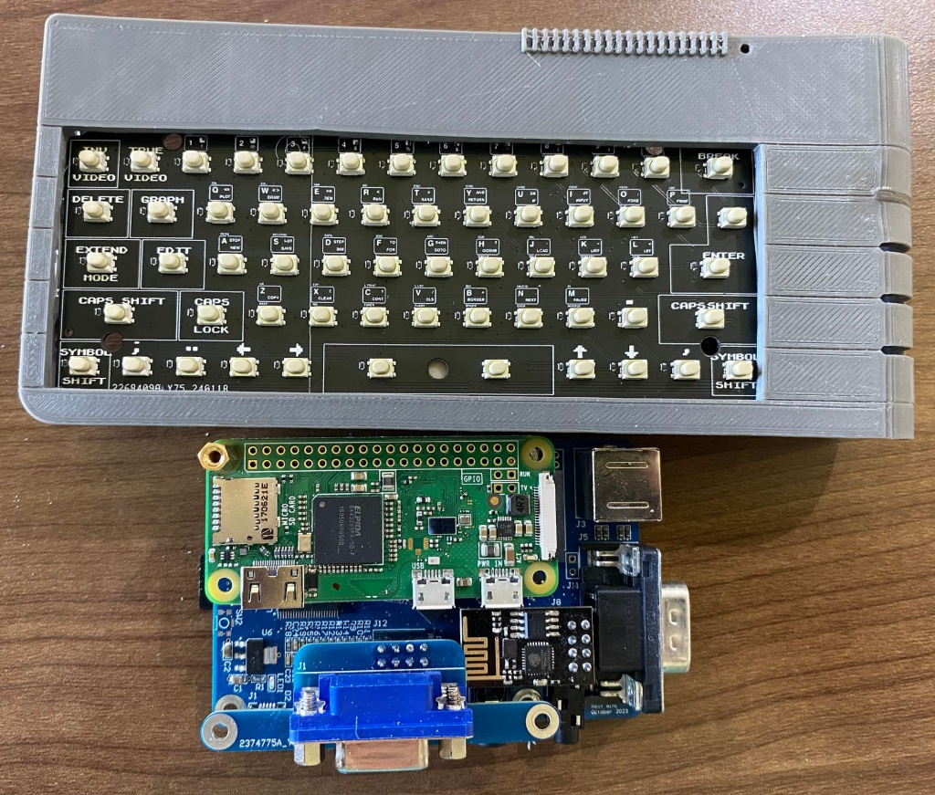
Have finally made the C64Mini one in surface mount – Now i’ve sourced a supplier of suitable, well priced keyswitches, I’ve felt it worthwhile to re-visit this project…
What SMT means – Very little soldering needed for this prodcut. Just the Arduino pro-micro at this time.
I’m hoping this makes the kit much more accessible, many will put their hands up and state that the 600+ solder joins needed on the old one was ‘painful’….
Some pics!

Top of the board – based on the modified 4.1

Bottom of the board..
Next step is changing the schematic over to use the much more readily available Raspberry Pi Pico or even creating a dual footprint board so you select which microprocessor to use, either the 32u4/Arduino Pro Micro or the Raspberry Pi Pico.
Unsure how i’ll offer the kits, I may well just pre-solder the microprocessor on so it’s a truly plug and play kit!
Still have to route the board, which will take a couple of days.
Also have started re-designing the keycaps from scratch – the old CAD is nigh on impossible to manipulate due to being so complex (was my first complex CAD project after all), so it’s easier to start over – and…I’ve gotten this far after just a week or so of playing
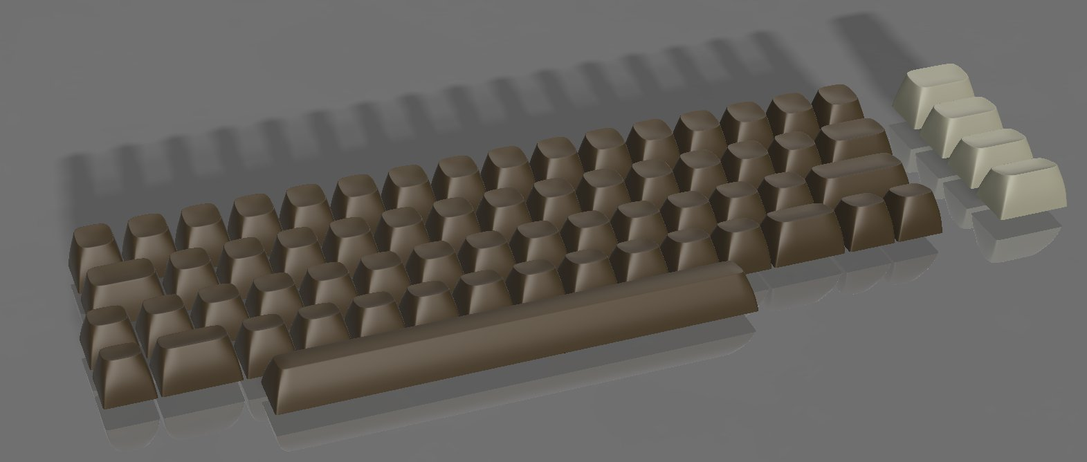
Keycaps re-done – Just needs the lettering and symbols!
I’m hoping to get this finished in time to add to my batch order of Next Mini and Amiga mini prototypes

I had somewhat of a PETSCII induced fever over the past few weeks, one that needed Sating before I could practically start anything anew, or even continue anything existing……..
So, when I (eventually) re-make the C64Mini keyboard kit to be less soldery, more easierer and betterer, It may well have PETSCII on those keycaps, for all your milliputty smudgery into-ey goodness!
A500 Mini Prototype 2 is in the post, Every C64Mini keyboard kit and parts have been posted – I’m finally fully up to date!
First print off the Mono-x

I’m having first layer adhesion issues – which is commonly caused by poor levelling on these things
Could also be a number of other issues but I’m confident I can get this resolved next week
The major fault on this one is that the bottom row of keys is all squished going to the right hand side, due to that side not adhering to the build plate correctly.
Have had another print literally just finish – with adjustments and that’s also come off the build plate so I’m really confident that I just need to try re-levelling again!

Apolgies for any delays and people waiting on keycaps….
I believe I may have reached the end of life of my original Photon Mono printer. for the past couple of months, i’ve been having more and more print failures, and have had no idea why. I’ve approached the problem analytically to figure out what’s wrong
Where it started –
I had a proper working file that ‘just worked’ – exposure about 35s for the first layers and about 1.8s per other layer
That started failing a bit. some keys were printing incomplete. I increased the exposure slightly and success again.
More fails, this time the first layers were coming off the build plate. I increased the exposure for the first 4 layers and success again.
had many minor creeps of fails, up to now where i’m at around 50s for the first layers exposure and 2.2s per layer.
I figured maybe the temperature in the conservatory is too low – Nope, iterating a bunch of exposures with the printer near the radiator in the living room also had nothing but failures.
So, after a good 15 fails in a row, many caused my me experimenting with extremes, i’ve given up with the photon mono. There’s many things it could be, but I’m thinking it’s feasible that the LCD has finally ‘failed’. I’ve easily gotten 1500 hours of actual print time on the thing – well over 1000 will be just the production keycaps at 6.5 hours each!
So, back to the point of the article. Those things in the picture are a R E R F TEST for my Anycubic Photon Mono-X
I’m dialling it in to start printing the keycaps. First one’s going right now (50% UV power, 3.5 seconds exposure and 45s base layer if you like to know)
IF this keyboard prints – fantastic, I can print two at a time in just 5 hours! i’ll be through the backlog in no time 🙂
Thanks for listening and sorry again for the delays!
Dean

A customer, Kopaszné has done a superb job with his Keycaps. Some acrylic paint and a few hours
The paints he purchased from Lidl are these ones off eBay.
https://www.ebay.co.uk/itm/254445322346
I’ve asked him to tell me a bit about the process he used, I’ll update when I know more 🙂
You guys (and gals) continue to impress 🙂 THANKYOU, every picture, message , feedback puts a smile on my face!
Download QMK TOOLBOX
Download the HEX FILE
Select the Downloaded HEX file from wherever you saved it
Select Auto Flash
Connect the USB arduino to your comupter
Short RST and GND on the arduino

Then, your arduino gets programmed! – Easy 🙂

Firstly, I’ve finally found the STL for the c64 mini keyboard kit keycap mould,
You can download it from my Google Drive – Here
Or from Myminifactory


The interest in the mini keyboard is strong as ever, but – there’s a new kid on the block soon – The Amiga A500 Mini
That Beastie –
To turn this Mini’s ridiculously small keyboard into a ‘toothpicks required to operate’ WORKING keyboard will be tricky as it has a significantly larger number of keys than the C64Mini
Infact, there’s 96 on European Keyboards and 94 on others? ..Either way – it’s More than 81 – which is the maximum you can put on 9×9 Matrix – which exceeds the capacity of the good old 32U4 when used as a keyboard (well, technically, the Pro Micro I use has 20 GPIO available, Allowing for 100 keys IF I go and hack out the two LED’s and solder a bridge)
So…Enter the Fantastic (and new) Ruby Firmware for Keyboards – PRK,
Which can be found here –
https://github.com/picoruby/prk_firmware
and, with a good overview – here on Youtube (in Japanese, but, enable Captions and translate to English, you’ll get the gist of it)
It’s taken me a Solid Month to figure out how to get this far – I’m a relative noob to Linux, cross compilation, Ruby, C, and, generally ‘stuff’ like this –
To be able to compile this, i’ve setup WSL for Windows – which is essentially Ubuntu Linux, running nativley in Windows!

I’ve also had to setup the Raspberry Pi Pico-SDK
Ruby – For Linux – something higher than 2.6
And a few other things….all of which are quite finickitey and throw a wobbly at the slightest provocation! – Linux is fun eh!..
I’ll eventually get around to step-by step documenting and linking each step to ensure a good build environment so that others can duplicate what I’m doing
Once it’s all compiled, I drag the .uf2 file over to the pico (after holding bootsel whilst plugging it in) the thing reboots and becomes a keyboard
What’s Next………..
Where this is going……………..The RP2040 Chip is fairly priced against the 32u4. I’m hoping that I can eventually switch the C64mini keyboard over to a fully SMT ready assembled kit – just add keycaps. And, i’m hoping I can do that for the Amiga Mini!, as much as I love soldering 600+ points, I appreciate some of you out there don’t!
And, I’ve another TOP SECRET project on the go also…It’ll blow yer mind! but, in 2022 that one, it’s a long burn that ‘looks’ finished (i’m holding it in my hands now!, all 2 circuit boards and about 100 3D printed pieces) but, needs quite a bit of work behind the scenes.
Also, Blinkenator, slow going, but I’m really trying, it’s just hard getting over this hurdle where it must be soldered….one last thing to try!
And, final before I go to bed, the C64 mini running the keybaord upgrade kit with pi Pico transplanted brains!
It’s being captured via a HDMI capture dongle and OBS studio so I can use my laptop as a test monitor!

Loads fixed with this – and it should hopefully be on Github soon also
The Hex File is above
There are only a couple of extremely tricky issues remaining now! they may need macros, and may not even be possible
Note with this firmware – It works perfectly with ENGLISH Language and UK Keyboard layout set in the firmware…
I hope to eventually be able to create more localised keymaps to change behaviour on boot so every language in the mini works well. IF there’s any pressing issues, please contact me, I should now be able to quickly and easily tweak a couple of keys for you.
Also, the Firmware will be part of the QMK Github soon, so you can download and tweak away yourselves!
To Upgrade your Keyboard, I’m finding QMK ToolBox to work brilliantly

Most older fimrwares out there will need to have B held down whilst shorting the reset jumper at the top of the keyboard inside , for whatever reason though t
I’ve found this a little flaky for whatever reason, sometimes mashing down every key whilst hitting reset does the trick
To make that more professional…….I now have configured the Bootmagic Lite.
To Update the firmware after this update, simply fire up QMK TOOLBOX, connect your keyboard to a Laptop. Hit ‘auto flash’, select the MCU (see picture above)…then Hold 1 and short the reset jumper inside the keyboard.
I’m still learning how configure all this, so bear with me, it’ll be slick just like those professional Mechanical Keyboards in no time*
*by ‘no tiime’ I mean potentially months and months as i’m tinkering in my limited spare time to add this extra functionality
Hi All – here goes
I’ve submitted a Pull request to the QMK Github to add the Mini !
https://github.com/qmk/qmk_firmware/pull/14159
And, here’s the firmware in a ZIP file to help
https://drive.google.com/file/d/1WVuZMWLF9_7ZtnlxLih7IebWrD0SbX_b/view?usp=sharing
That’s the QMK Code For the Arduino used inside the C64 Mini
How To Compile
Download QMK – I recommend QMK MSYS. Get it installed
There’s plenty of tutorials around
BUt, quick and easy – Unzip the above file to the KEYBOARDS folder
C:\Users\YOURCOMPUTERNAME\qmk_firmware\keyboards\
Then fire up a command prompt (Start, search, CMD, run)
and navigate to the the above folder
then run
qmk compile -kb c64 -km default
You’ll get a c64_default.hex file appear in
C:\Users\YOURCOMPUTERNAME\qmk_firmware\builds\
Now to flash –
Download QMK TOOLBOX
Arduino leonardo’s can be a little tricky to flash hex files to – be persistant – there’s two Tools that help
QMK TOOLBOX – that shows the keyboard enumerating when you plug in
Set it to ‘auto flash’ and you can try pressing / holding b and space (it’s configured as a magickey in QMK) to get the bootoader to kick in and flash the chip

If anyone knows a quicker way – shout!

And, if it helps
No PCB gerbers are public yet – play away! any suggestions, happy to look at incorporating them
I’ll follow in the future with more insight in how this lot works, and also modifications needed to get it going better… There’s a LOT to it as the Keycodes – https://sta.c64.org/cbm64pet.html
Don’t map to the HID codes used by USB…so, without some super customisation, certain combinations may never be possible
Some useful resources
https://www.c64-wiki.com/wiki/Keyboard
https://github.com/qmk/qmk_firmware
https://github.com/qmk/qmk_toolbox
https://thec64community.online/thread/688/c64-keyboard-mapping
and a few other C64 USB firmware’s i’ve found – these may have the bits needed to be able to get mine working much better – But, merging things is currently beyond my skillset – I’ll figure it out eventually
https://symlink.dk/projects/c64key/ – Has seemingly sorted out shifting, etc with custom codes. I can’t quite figure it out though
And, this awesome public project! – If you want a ready made USB interface – This looks great. Has some quite complex QMK mapping that i’ve not been able to understand – maybe it can be modded for my PCB!.
Wow, What a few weeks this has been.
My previous QMK on my small dev laptop worked great. However, moving the directories over to my new laptop (after the kids smashed the old one) – Not working so great
I was now stuck with a handful of ‘blank’ arduinos and no way to update the firmware code, nor any easy way to flash the .hex files to them
Long story short – a friend familiar with programming Arduinos found me this
https://github.com/p1ne/arduino-leonardo-uploader
It didn’t work!….BUT playing aroudn. it at least did pickup something
So….Digging further…I found
https://github.com/p1ne/arduino-leonardo-uploader/issues/5#issuecomment-407583517
I tried the code, didn’t work
Tried again and………Woooo!
So, where i’m at now……
I can actually program up arduinos for Mini keyboard kits!
The printer actually seems to be functioning
I’m back in Business
What’s next though
Figure out QMK, I’ve found a lovely chap who’s helping out a bit to compile my keyboard into the new version of QMK being used….then I can finally start doing some development again!
and, more importantly, get this C64Mini keyboard listed in QMK for you guys to be able to easily play with the firmware….
Having some fun with the printer this past few weeks. many, many fails

Lightly used, honest
Some possible lessons learned….
1 – Don’t mix Resin brands and pigments in untested combinations
I’d ordered a bunch of ‘expired’ Elegoo translucent green resin, going ridiculously cheap, (like 1/3rd the price it should be) it prints FANTASTICALLY…BUT
….I normally use Anycubic Clear, just because it’s what i started with, and it works.
I also add various pigments from http://resin8.co.uk
Mixing in an old batch of C64 Brown with the new Elegoo didn’t really work. I had 6 failures in a row – which i’d assumed was the FEP or me doing something silly / bad levelling . The 7th failure punctured the FEP! At that point i’d realised what i’d done (mixing all the stuff together) so, ordered some new Clear resin. I got a perfect print straight away!
The thing you see above is me, changing the supports (finally) after having issues with the old base layer being too thick and seperating from the build plate. I’d gotten around this by using longer base exposures, but still, had more failures than I’d like.
Hopefully now i’ve new FEP, new resin, and spent a couple of hours doing the supports properly, I’ll get a fresh print tomorrow!

My next issue – as you can see above…QMK. I spent weeks learning how to, and setting up QMK on my old laptop, which the kids smashed.
QMK has moved on a little it seems as now there’s a dedicated QMK MSYS32 installation…BUT, it doesn’t compile my old keyboard layout. if there’s anyone good with QMK out there, give me a shout!. I’ve no doubt I can get things working again to work on the code a little, just pressed for time for the next month or two and, i’m getting the coding itch this past few days 😛
Firstly, if you’re interested in a kit, reach out via email
KEYBOARDS AT BLEUGH.BIZ
you can also find me lurking around facebook, reddit, twitter!
Two brands have been successfully used to colour your keycaps
1 – Milliput Epoxy Putty – (Thansk DAN) Available here – amazon.co.uk/dp/B002CNEWAM
2 – Stucco K2 – (Thanks Vinz)
available in Italy.
For you English, This translates to “paste for interiors”….amusing that PASTA=PASTE…no wonder some stuff we ordered a few years ago in venice came a bit squdgy 😛

Use a damp cotton bud or similar type of thing to poke a bit in at a time and not get it everywhere!…leave to dry. clean up, then coat with some type of laquer or conformal coating if you really want!

Lots of pictures here, But looks like the latest batch of C64 Mini hackers are quite the clever lot. Batch 21 has been arriving around the globe, and look wot some guys gone done!

First email arrived early this morning – Vinz!, You’re a genius…..My jaw dropped!
Some explaination of the pictures…….
In photo 1, I used a ruler with double sided tape to solder switches as straight as possible
in photo 2 I used white putty to color the caps
in photo 3 I cleaned the excess putty
in photos 4 and 5 I painted the caps with matt transparent water-based paint, in this way the filler is protected
in photos 6 and 7 the work is finally done
Continue reading “C64 Mini Keyboards – COLOURED LETTERS! (by end users)”Phew, what a mad few weeks.
If you’ve paid for a kit or just keycaps or waiting on spare parts, it’s now posted.
Missed the Saturday run to the post office so sorry about that.
I’ve now a small amount of stock of keycaps and plenty of kits so I can relax a little and have fun printing other stuff for a change! Can you believe that I’ve run at least 6L of resin through the printer …JUST developing and then selling these keycaps, I’ve never printed anything else on it 🙂
A quick pictorial ! on the process of creating keycaps.


I’ve missed out a few pictures, but this covers the basics. Using a timer, it’s around half hour all-up per keyboard. Sometimes a little more if a print fails!

Tried to make a ‘GOLD’ keyboard but need to research a little on how to keep the particles suspended. This one failed due to too much gold. It all sunk to the bottom causing layers to become underexposed and ultimately sticking to the FEP

Also tried to make a crystal clear keyboard…unfortunately I topped up the vat with a tiny bit of the gold mix from a poorly labelled bottle I use f or mixing (I didn’t write any label!) I’ll give these away with a kit to the first person that asks 🙂

Quite late into development, I’d realised that the F keys were supposed to be a different colour. So, I add two sets of F keys to kits. Some early ones went out without the extras. Happy to send some out if you shout.
Thankyou everyone for your support! Sold quite a few more kits with keycaps than expected so frantically printing away more!
If you’ve paid for a kit or just keycaps, they’re all packed and ready to go! Should take between 3 days and 3 weeks depending on where you are on the planet!

I’ll hopefully be getting more time to update on other things soon 🙂
Hi All. everyone that’s expressed interested has bought up a kit, thankyou all. I now have general stock of unassembled kits available for immediate shipping
I also have stock of keycaps!
Have finally received the switches. Couldn’t find my multimeter so quickly tested the orientation was correct with a battery and LED.
Have now bagged them and have enough kits ready to fulfil those on the waiting list.
I’ll email everyone tonight and wait a week before I make kits fully available
Thanks for your patience everyone!


Switches will be here in a day or two!, i’ll email everyone about kits shortly.
Purchased some ‘old gold’ pigment from https://www.resin8.co.uk/ and tried it with the keycaps for something different. Came out ‘ok’ – nice and gold on the top, but lacking in gold on the sides. I suspect the particles weren’t being agitated sufficiently and sank to the bottom.
I’ll try again soon with a higher concentration of pigment and see how that goes before considering offering these as a product!
Was just about to order another 4000 switches and take the hit…Decided to check the tracking number and FINALLY, after a month in Limbo, the switches have been released from Liege, the infamously slow sorting centre in Brussels.
SO, should be here next week and i can Finally get sending kits out!
Sorry again about the delays, I’ve now bought excessive stock so, should be able to turn around things quite quickly.
also built up a little stock of the keycaps which can be included in the kits at no additional postage cost
A quick post to show the keycaps being sent.
There’s no painting,
The letters are recessed into the keycaps and are very legible.
I’m working out postage costs as right now they’re still large letter in size here in the UK.
I probably won’t ship all of them them ‘on the supports’ as that doubles the weight
To fit them you just clip them onto your key switches


Painting. I haven’t been able to find an effective way to do that my end. A few suggestions have come in, maybe White clay would work well finished with laquer.
Hi All,
I’ve now packed up 10 kits ready to be shipped and have emailed the first 10 people on the waiting list.
It’s been an expensive couple of months with the bad PCB’s and wrong arduinos, but, payday at the day job was two days ago, so i’ve already ordered enough additional parts to make everyone happy within a few weeks
I’ll work may way up through the waiting list and let you all know when I can finally make general stock available.
My New PCB’s will be here today! DHL shipping is expensive, but great when you need stuff quickly!
What this means – I should have general stock next week.
Timeline – I’ll get a test board built up this week. if that works, I’ll email out everyone who expressed an interest.
I’ll get everything kitted up through the week (time permitting) so I can get some posted this weekend.
The rest of the weekend will be spent kitting up everything I have so I can start selling again.
Sorry for the delay guys (and gals). Been a perfect storm of wrong components sent, big customs delays, non-functional PCB’s. I thought the ‘march’ timeline was generous and had plenty of padding in for worst case.
For general availability, i’ll be reviewing the price. Most things have gone up by over 20% in general (Brexit, Yaay), some have come down, and i’ve made some optimisations. These projects aren’t a get rich quick scheme for me, they’re just a way for me to get funds together to buy more tools and things to make more projects! It’s pretty much a cost neutral hobby 😛
One final update – Keycaps. I’ve started manufacturing and at the time of typing, I have sent out a few test items to kit owners. I’ll await some feedback before I can hit ‘go’ and make more.

Those are just some of the prints i’ve had to do to get to where I am now. This isn’t representative of the typical resin printing workflow. its generally a bit easier than this, BUT, I had to start from scratch, learning how to do everything, including stuff that hasn’t been done by others. AND I needed the base level print to be ‘perfect’ to avoid the need to paint them. There’s over 80 hours of actual printing time in this picture, on top of that, there’s the cleanup time, CAD time, setup time….these are the ‘successful’ failures, there’s almost as much again that i’ve binned due to total failures, where keycaps were unusuable for anything, not even experiments (as these ones have been used for). fortunatley most of those failures were caught early to avoid too much wasted resin….but when I get only 1 chance in the evenings on some days to quickly iterate, get the printer going, 1 failure can set me back a few days.
Anyways, now i’ve finalised everything……..
I’ve used an entire bottle of resin over the last couple of weeks making test manufacturing prints back to back to tune the process, changing nothing, just print, print, print… By that, I mean, it’s…
I’m now at about 70% success rate for good saleable keycaps. the other 20% have minor blotches or surface uniformity issues, so i’ll sell those discounted for those that are interested. I’m still getting about 1 in 1o that can’t be used in any way.
Good enough, and i’m sure i’ll get better as time goes on. Each print takes 6.5 hours – slow, but reliable and a 25uM layer height so about as good as it gets on resin printing for surface finish.
Each print also takes another 30 minutes or so to ‘turn around’ –
And, Pack some up, ready for posting I have! I’ve done a mix of ‘on the supports’ and ‘loose in bags’ to see how these things go. I’ve posted a couple to myself via friends overseas to see if they survive!. once I know what i’m doing is working, I’ll make them available for sale!

8 sets of keycaps ready to go, waiting feedback from testers before I can ship!

CAD is final now! The keycaps fit perfectly . They latch on with a push and can be removed!
Continue reading “Nailed it! Commodore 64 mini keycaps.”The mechanical, fitty holey type tolerance, not the other type of ‘oh, that’s annoying, but i’ll put up with it’ type….


Here’s the keyswitch fitting into the space bar. zoom in. we’re talking fractions of a millimeter fit, which I can achieve consistently and reliably! there’s about 0.1 mm available on the sides with the latches and about 0.2mm availavle on the longer sides. the extra really being there to allow some grace when placing the keycap on to fit it. less clearance means it’s a royal pain to get the switch located into the hole.
BUT, the keys don’t ‘latch’ into place on the switches. So, to try to address that (if it’s even possible) i’m now adding a small feature

This is the underside of one of the ‘F’ Keys. That small part in blue is a 0.1mm ridge sat about 0.8mm up from the bottom and 1mm from the top. I’m hoping that will be enough to latch the keys on, AND allow ease of fitting without breaking the keycaps. Everything else is done now, this is the only barrier to releasing. I’ll run off a print tomorrow to see how it works out. I’ll run off further prints with this sticking out even more if i need to

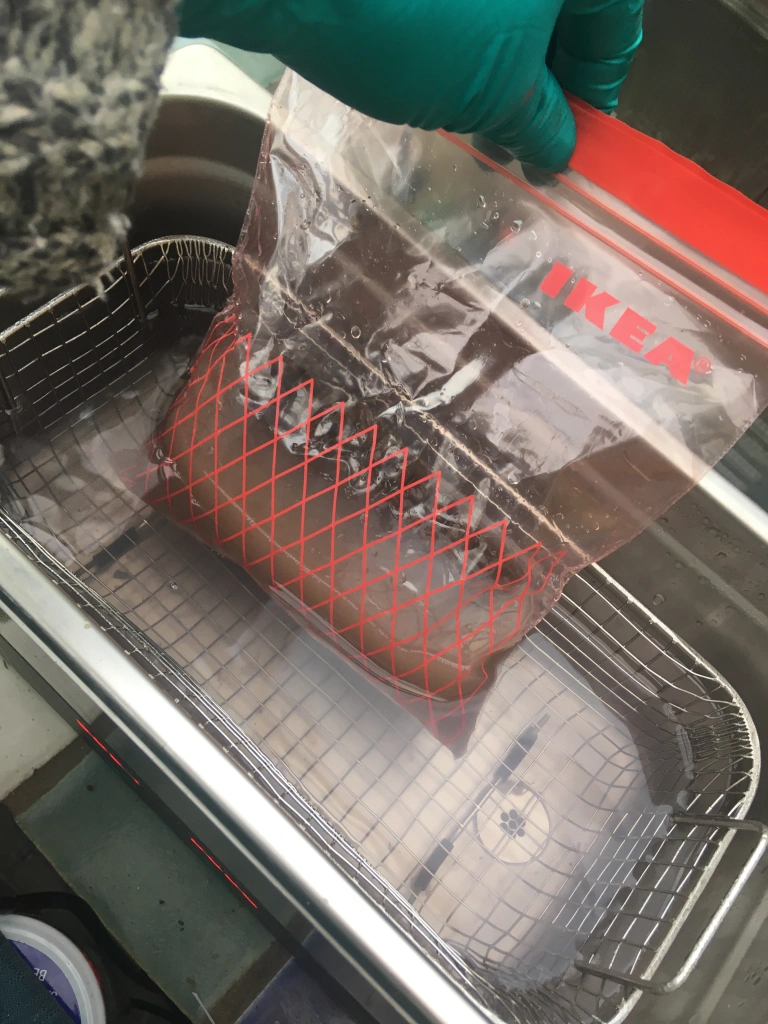
Happy chappy this morning. They finished printing last night, my draining widget worked a treat – I’ll put a quick GIF up soon.
But, forgot about them until a mad panic at close to 1AM remembering I’d left them on the printer. With these, you can’t as the resin in the concave surfaces will part set in the morning and cause an uneven surface.
So, quickly washed them in IPA, regretted it immediately as it was dirty. Did another wash in IPA to clean the resin and straight to the hot water tap and larger bowl with a brush to clean off the bits. I’ll strain out the bowl later.
Final tweak needed now is the amount of grip to the switches themselves, shrinkage is variable at the moment, can’t go too small or keycaps may break when putting on, can’t go too big or they’ll be too wobbly and fall off.
May need to go middle ground and require a tiny blob of something sticky in each keycap, I’ll know soon enough!
The final hurdle for ‘good enough’ for me now is the space bar.
Every key prints lovely, except the largest one……Take a look

I’ve gotten all the ‘hard stuff’ over and done with first, or so I thought. Life’s taught me to generally avoid going for the low hanging fruit first, save the easy stuff for later when you need a boost.
Well, no matter what i’ve done (so far) in 12 iterations, have I been able to get a good looking space bar.
Now this has become my sole focus and roadblock for a successful print
Turns out that this is a combination of quite a few variables, I’ll list a few and probably follow up another time with clicky links and research
My solution……


Probaly waaay too many supports, but this way, each ‘sag’ will be between supports that are just 1mm apart.
I’ve also nearly doubled the wall thickness to about 1.8mm – from 1mm

Hopefully now, this is the last step, Colour’s good, CAD is good, Supports are good.
I’ve ordered 2 Litres of clear resin ready to go and have a colour that’s not exact, but close and, importantly , very easy to re-create
Resin8 Earthy Brown, 3 ‘blobs’ of the end of a lollypop stick to 100ml of resin. and Black, 1 blob.
– The Rich brown used previously was too red. I’ll experiment a little with more black when running off the final tests
https://www.resin8.co.uk/opaque-resin-pigment—earthy-brown-7468-p.asp
https://www.resin8.co.uk/opaque-resin-pigment—black-2383-p.asp
Coming soon!, more kits in stock, and Keycaps – March 2021!

