It’s been a couple of weeks of iteration and maybe ten actual prints between these two prints!
In person, the difference is very notable. more subtle in pictures.
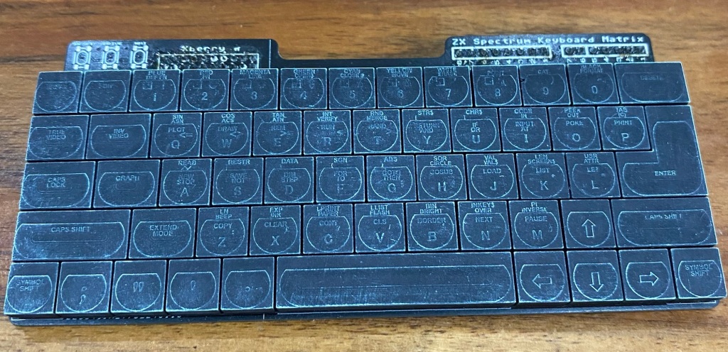
This is as good as it gets for a standard set of keycaps 🙂 I’m finally happy.
Now I can really get stuck into experimenting with getting those legends white! I have three ideas, one may be limited somewhat by the viscosity of water!
Should be here next week, not long till I find out how badly I’ve cocked them all up and how much work needed for a re-spin for production!
I purchased 2000 switches so can re-spin and re-test one, possibly two depending on which one (the Amiga needs 500 switches for 5 keyboards, spectrum needs far fewer!!)
Exciting times, now gotta get off my bum and fire the resin printers up.
Yep, these are WORKING keyboards for the
The A500 Mini Amiga
The C64 Mini Commodore 64
And
The Spectrum Next Mini (an Xberry Pi case) which is a 50% X &Y (100% Z) scale next mini styled case.
Back a few years ago, I ventured into making my first PCB in over 2 decades. it was motherboard to hold a raspberry pi zero, and fit within a zx spectrum case.
it was inspired a little by an article in MAGPI magazine by a Mr P J evans.
I did kind of goof it up a bit, so relegated that to the ‘ideas to do in the future’ drawer
Been a busy few weeks here at Bleugh.Biz industries, working ridiculous hours at my day job, keeping kids from murdering each other during the evenings……But, i’ve been getting some good tinkering time in.
Some very good progress has been made! – and this is the board that’ll hopefully, finally, once and forever physically fit perfectly
Some Notable changes
Balls! – A revised J15 connection method that’ll provide a simple and very robust connection method
Spacings – The holes for the LED inserts have been altered a little to allow easier assembly. It’s still mildly fiddly but easy enough.
Fixtures – The J15 are has now two horizontal slices cut into it – this provides a spring mechanism for the balls. it helps to PCB distortion locally without warping all of the board from Next PCB to inserts
Holes – The whole board is now held with press fit type connection. The two screws holding the Next PCB are removed and replaced with two new ones. this holds the Blinkenator board to the next PCB and the Next PCB to the case. The two holes for the screws have been changed to 5mm!
Positions – The JST style connectors have been re-located and changed from Right angle to Vertical. Now the board’s mounted above the next board there’s plenty of space underneath. The path from the Arduino USB connector is now also free so you can tuck a cable into the board permanently
LED’s – Moar Bling! Each insert location now has a LED colour on the main board. No real purpose other than to look great and provide the end users with some assurance that the board is powered up when they do their first tests with a USB cable outside of the Next
ESP-01 – CPU_RST has been changed to a JST style connector to make ease of fitting. This whole feature is still highly experimental and may not make it into final production (if it doesn’t work, there’d be no point!)
Inserts – There’s now a 0.56mm gap between the jumpers – to fit a 0.6mm wide PCB!. makes a nice snug fit. and easy also to work with – simply trial fit once when you receive your board, that’ll loosen them up. remove and re-fit into the Next
Jumpers – Lots of experimental jumpers! GPIO to arduino, TX/RX to arduino, DB+ integration enabling / passthrough…….and some secret sauce also
THICKNESS – The board’s back to a phat 1.6mm thick. this provides significant stability to the jumpers that hold the inserts in place. Much easier to repeatedly get them soldered straight when assembling
Components – The whole board’s been rationalised for component price – and where possible using @JLCPCB’s BASIC library – that saves quite some amount in production prices as non Basic items incurr an engineering fee per component. Previously 3/4 the components were Extended, now 3/4 are Basic!
Silkscreen – Tidied up and made a bit more slick……..
I’m sure there’s a few more changes i’ve missed, but that’s the important stuff.
Where from here……….IF this last board plugs in, fits well, i’ll be sending out to the key Dev team. I can then kick back, relax a little and start again playing with the software side of things, Both Next side and Arduino side!.
I’ll eventually also need to consider switching over the whole board to SMT, or as much as possible. I’m not that daunted by this as there’s quite a number of ways this can be achieved, including just putting the 32U4 straight on-board, or considering changing the micro type entirely. After all, the main reason i’m using a 32u4 is that it’s cheap, Arduino compatible, has USB built in. All those things give a great ‘dev board’ capability that people can use to simply plug in and tweak!
to use some PCB grounding spring contacts to provide a quick fit connection didn’t really pan out – the contacts simply didn’t solder on easily, too difficult to align correctly and quite weak – I tore a few pads off trying to get them aligned and correctly ‘grippy’ on the insert.
multiply that by 16 each board – the first one took me about 2 hours to get to be in an ‘ok’ state – Not really acceptable for a mass production product – not that this’ll be mass production but I’d rather not spend half a day on each of these getting them ready for sale……..
The second slight issue – See the photo below
The PCB is laid out on top the next board in the position it’ll be installed in.
There’s a prize for someone that spots the goof-up
Have a further look at the PCB powered up………..
First Light! – The board works 🙂
Yeah, I got the inserts ‘back to front’ – That’s the result of working on a bottom mount PCB from the bottom…….
There’s two ways I can fix this
Simply rotate each LED by 180 degrees on the PCB and install a bodge wire to swap the input and outputs around………
OR….
I can simply re-design the LED insert and improve upon it!
a few reasons to re-design,
The first 6 LED version still has a bit of point brightness – I fear that even with the SLA printed inserts it won’t be diffuse enough..
Some statistics
8 LED’s – This should spread out the light more, reducing the hotspots a bit
0.4mm Slimmer – this lowers the LED’s further into the case, allowing much more plastic to sit above. I’m hoping this will de-focus the light more
Reversed connections to match the reversed controller board!. reversed is the new non-reversed now 🙂
New insert PCB’s are on order and should be here in a couple of weeks, I’ve bitten the bullet and ordered FIFTY….Also a few hundred more LED’s and a large tube of solderpaste.
Doing these first 10 dev boards is going to be fun – 320 1.5mm LED’s to be hand soldered!
The Controller board fits inside the case almost perfectly
I’ve slightly offset the J15 connector on my PCB to the one on the next. This offset gives a lot of friction, but needs some long term testing – the standard header I installed on one of my boards seems to work well as a friction fit. BUT, i’m not convinced that 32 LED’s, each pulling 5-20mA, (depending on which datasheet I refer to) – or between 160-800mA total depending on how I end up setting the brightness…..800mA is a LOT to pull
I’ve purchased a new gadget – A Riden RD6006 Benchtop ‘power supply’ so once i’m set up, i’ll charaterise the LED’s and current draw to set the software limits appropriatley
I doubt i’ll take nearly an amp on this board 😛
One further small mistake on the dev board –
That 3V3VCC – it should say just VCC
When originally designing this controller board, I was to use a 3.3v Arduino to make it compatible with the Next’s 3v3 i2c.
For a few reasons, I’ve changed to using a 5V arduino and putting on-board a level translator device – this gives a 5V buffered i2c output that anyone can easily plug into
I forgot to change the net names….The board still ‘thinks’ the Arduino is either powered from RAW (it’s ‘unregulated input’) or 3V3 VCC…
The RAW input drops a few volts through a voltage regulator on the arduino to give the arduino a nice regulated 5V.
The next output is 5V….it’s not enough to power the Arduino through the RAW pin…
Took me quite a while – and a bit of soldering hackery to figure that one out as the speccy picked the board up perfectly when patch wired in place..
USB powered, it works perfectly
in the Next it doesnt….
The fix – I think I can just short the RAW pin to the unconnected VCC pin on this first batch –
and, finally
See that i2c device, found at address 0x45………..That’s the Blinkenlight 2000 PCB :-), alive and inside the Next!!!
Had a little bit of a play with the daughterboard to see if there’s any possibility of putting a ‘push push’ SD card inside…
Unfortunately it isn’t without chopping at a couple of supports inside. I’m trying to keep my Next case fairly minty – untill it’s possible to get another, i’m going to avoid this mod.
The reasons it won’t fit – The case was designed with two ‘helper’ guide rails for the SD card – shown in yellow in the images above. Those rails stop any push-push mechanisms from working – there’s just not enough mounting depth for the card reader.
Now, if someone were prepared to snip those rails off….then it’s entirely possible to knock up a new daughterboard……I’ve already done most of the EDA before I thought to take the next apart and check 🙂