Should be here next week, not long till I find out how badly I’ve cocked them all up and how much work needed for a re-spin for production!
I purchased 2000 switches so can re-spin and re-test one, possibly two depending on which one (the Amiga needs 500 switches for 5 keyboards, spectrum needs far fewer!!)
Exciting times, now gotta get off my bum and fire the resin printers up.
Yep, these are WORKING keyboards for the
The A500 Mini Amiga
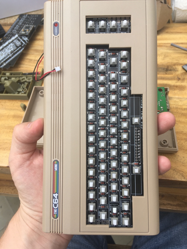
The C64 Mini Commodore 64
And
The Spectrum Next Mini (an Xberry Pi case) which is a 50% X &Y (100% Z) scale next mini styled case.
It’s taking way too long, but I think I now have the lettering ‘just right’ – at least on the screen.
This was printed a bit too hastily at 0.08mm layer height on an Ender 3 printer. I’d used a brand new roll of untested filament and didn’t bother changing any settings. – it’s dimensionally ‘spot on’..
I’ve purchased a 0.2mm nozzle for my next trial , it’ll take ages but i’m hoping that those fine details on the characters come out a little better.
Why it’s taking so long……..
I’m learning as I go. I’m ‘tracing’ letters i’m finding on the net, creating them as a new sketch along the whole rows. There’s 4 differently angled rows so each needs to be extruded in a different direction to ‘cut’ the key.
This first run matches the C64 keyboard font as close as I can get. I’ll then ‘archive’ this layout for future use and create a second ‘3D print’ version.
This version will forgo the accuracy of the font and make features much wider, more rounded to allow the characters to come out better once 3D printed. The complex ones like ‘run stop’ won’t ever come out great on a standard filament printer, but the letters already come out pretty good…that’s a win for me!
a full keyboard!
The full keyboard is above – and you can see part of one of the adaptors i’m designing to click them onto the keyswitches. each keycap is hollow. that small grey part will sit inside the keycap
Where the time’s being spent…..
And finally – part of what’s taking so long.
Each key/character is taking on average about 1/2 an hour to an hour to design. Lets say 45 minutes.
65 keys to label
That’s a LOT of minutes…and i’m only getting an hour or two every few nights – a good solid weekend ‘free’ would be great and have this sorted.
On top of that labelling (which is now finished) I have to try to make each letter more legible and easier to 3D print. Generally that means ‘bevels’ everywhere – you can see above that i’ve done ‘Run Stop’ and ‘Shift Lock’ but SHIFT is still to do….it’s not as easy either as ‘copy, paste’ the Shift from Shift lock – that’s a different sized font on a different sketch plane.
Just one example of the issues I’m seeing…The Letter B
The Letter B – trying to create a fillet – rounding off the edges
The Letter B above has an issue with the geometry – just by the 0.1 – there’s a part internally up towards the arrow that shouldn’t be there – that’ll could play havoc with a slicer when set to really small layer heights
B – Alternate view
But, the Fillet also creates a zero thickness surface which looks unsightly and will probably cause issues if I don’t correct it now
So, Back to the sketch
Letter B – The Sketch
As you can see, i’ve kept the characters with few (if any) constraints. this way has been easier to freehand and eyeball as I can drag stuff around till it looks right by ‘locking and unlocking’ lines. most constraints used to create right angles, etc have been removed after to help with the process of making it 3D
Anyways, the ‘issue’ with the fillet seems to be around the place where the two control point splines meet – i’ve highlighted one in blue above.
I re-coincide each spline (have found deleting and un-deleting works, as well as hitting coincident )
That change should hopefully roll back up the timeline to allow me to make the fillet work.
To Create the key lettering I the character by 1mm elsewhere in my workspace, then move it to over the key.
Then extrude the face of the character into the key and ‘cut’ ….
this may seem odd, but it’s a really quick and easy way of consistently creating cutouts on a row of keys and making quick changes later.
That didn’t work, so, jump into surface mode – delete the entire inner arc of the B. Re-create the arc as a ‘patch’. Stitch together the lower part of the B. Then stich the whole keycap, then re-apply fillet and…..Voila…..3/4 an hour later, one filleted B…And a learned workflow if the same thing happens on another key!
Note, as-is, the keyboard fonts are a bit innacurate. I’ve sized everything based upon the smallest characters that need to fit – i.e. run stop, etc. The individual letters could be bigger – but any bigger and they’d look too big compared to those……….
Next steps,
DFM – Design for manufacture.
Just because you design a 3x2mm hole, doesn’t mean it’ll print at 3×2. Generally Filament printers do outer perimeters a little larger, inner perimeters a little smaller. The first few tests i’ve done now prove this. so, After a few months of ‘out of the box working’ on my Ender, I’ve finally gotta bite the bullet and calibrate it. The plan is to create an offset in the CAD file so that I still design the holes accurately based on measurement, BUT, can add a accurate ‘calibration figure’ Fudge figure to make them a little larger or smaller as necessary.
Right now my Printer is doing slightly oval prints – which should be easy enough to sort out if my D9 Adventures were anything to go by
Lovely and sunny outside. I’m in the conservatory kinda enjoying the outside………Through Hole Diodes should make for an easier assembling kit
My Kids hate me, my wife’s lonely but the march towards C64-Mini Keyboard workery continues – That and they let me have a few hours to tinker on the weekend!
Figured whilst assembling the new boards, I’d see just how long it takes to solder them….
Quite a while as it turns out
1/2 hour to solder in 65 through hole diodes
1 hour to solder 67 switches
another 1/2 hour testing and programming
So, about all up, we’re probably talking 2.5 hours for me to fully assemble one of these…….
Except, that 1/2 hour of testing and programming actually turned into a 5 hour ‘session’ of bug fixing / fault finding – one of which…..
One of these is not like the other………..
A back to front key causing lots of characters to repeat accross the screen…..M, Space – which are both on the same column of the matrix too!
Fixed that and have discovered that it’s not really possible to re-use the switches once you’ve soldered them in – UNLESS you use a hot air gun to remove them. I’ll definitley include a few ‘spares’ in each kit
The next problem – A sticky, grindy P key – I lifted a pad removing it , fortunately, the pad wasn’t electrically connected – only 2 actually are – which will save you some time! – just solder 3 holes for each switch – that’s 201 solder connections for switches instead of 402!
The next problem…the Fantastic QMK Just refused to work and compile 😦
Kept getting “qmk avrdude.exe: butterfly_recv(): programmer is not responding” the thing just wouldn’t work over USB like the others had
which turned out to be a couple of things.
You can’t use AVRDude when the Arduino IDE is open…
Arduino Leonardo type devices (well, the clones anyway) can be a bit finiky with the USB…
Generally sending them a ‘blink’ sketch does the job…BUT, they very often need a quick ‘double tap’ reset pin to ground whilst uploading……..that’s why I have a RESET header on this board – if you want to solder one in, feel free, it’s mainly to help me when developing it.
Another issue was the frequency setting in the rules.mk file – I’d previously used a 5V Arduino pro Micro (Atmega 32u4) , somehow a 3.3v one had snuck into my spares box – these run at 8MHz, not 16MHz
Changed the firmware, recompiled and……..It’s alive!
First row lined up – second just tacked on with a single joint, ready for lining upFinally added a bit of heat shrink
Straight!, got the technique sorted – Note the two that are slightly ‘off’ to demonstrate what happens when you change the way you ‘hold’ the switches when flipping the PCB to solder
The case fits the keyboard like a glove!
Also got a bit of a chance to progress with the CAD……
This one day may turn out to look like pretty rough keycaps! mini ones! for a mini computer!
After a few days, I’ve now got something workable – The switches being Thru-hole allow ease of routing on both the top and the bottom layers. I’ve named each switch and diode with the keyboard’s actual Symbol to make placing them on the PCB much easier. you’re seeing the results of a few days work (maybe about 4 hours all up) of starting from scratch on the design.
Next step will be aligning the PCB layout and spacing with the plastic buttons
I’ve done what I can based upon rough assumptions above – the top row of switches for example – its row of buttons ‘just’ fits within my calipers – so it’s about 151mm wide
As mentioned before, there’s loads of ‘keyboard matrix’ tutorials out there, so, i’m going to not bother with any of those yet and work backwards a bit.
IF i’m making a micro C64 Keyboard for a mini C64, I mayaswell make the thing backwards compatible so that it could be used on a real C64…
The Shift Lock key looks a bit ‘odd’ as it just parallels up with the shift key.
I’ve thrown in some Debounce diodes also – because all the top mechanical keyboards have it, so why can’t I (no idea if this is a good idea yet, but easily removed before I get a PCB finalised) I’m not too worried about the Arduino bits yet – i’ll bolt on the decoding circuitry later – this is still just an excercise to see if it’s possible!
This isn’t the first version – The pic shows the newest footprint before I figured out the issue below
After creating my own custom SMT switch footprint / component and arranging the parts on the board – I hit a few snags – Have a look at the layout below…. you’ll see that the SMT legs just stick too far out
Easy enough, rotate every other switch so some are ‘up / down’ , some are ‘left / right’ with the pads.
That does fit – just, BUT, i’m going to have to cut a leg off 5 or more switches to stop them mechanically fouling and electrically shorting!……D’oh!, Possibly back to the drawing board with the switch choice?
The diodes i’ve chosen (for now) are a larger SOD123 package, about 2.6 x 1.5mm or so…one of the larger packages and I just happen to have a few in the shed (somewhere!)
The row of connectors on the right is just a generic 2.54mm space 20 way header. This’ll probably not be populated in my ‘final’ version that sits inside the Mini, BUT, i’ll leave the pads on the PCB so it could be turned into a genuine working C64 Keyboard 🙂