Another un-interrupted few hours of Laptop time and I’ve now gotten to the point where….All the stuff fits. Now it’s just small tweaks, printing and ‘production’ .
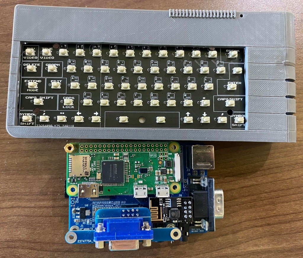
To get the PS/2 from the XBerry pi to the correct place on the rear of the case, I’ve put a small 6 pole ‘helper’ header over on the left.
Much Improved PS2 Port location – you can see the connector inside is now moved up and in-line with the other things!
I’ll then use just the small insert connector pins bit of the PS/2 connector and hand solder some wires for the first run. I might then make a fancy PCB for a final ‘final’ version
I’ve also now added a PS/2 port to the ‘rear’ of the keyboard PCB to save having a 4th custom PCB. For those that want ‘just a keyboard’ i’ll not be populating the rear side components (other than the Pi pico)
I’m now happy enough to pretty much freeze any problem solving, everything’s been solved now, so it’s down to relatively minor clearance and fitting tests now!
I’ll no doubt] need a few small revisions anyway and I’m really itching right now to make this thing Physical so soon, i’ll start using the 3D printers again, and be able to start back on the A500/ C64 and Blinkenator development!
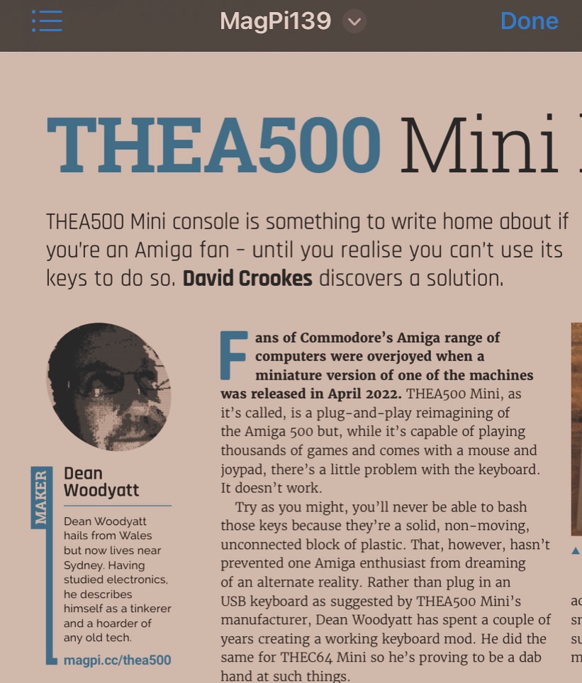
It was the 12th Anniversary of the launch of the Raspberry Pi . I was one of the fortunate owners of the first ever First 10,000 units. Fell in love and have purchased tens of the things since.
They also released an official magazine to accompany the product – The MagPi Magazine
Today, with the release of Issue 139 my Amiga Mini keyboard project has been featured over two pages 🙂
I’m chuffed to beans!
Go buy your copy in the shops next week, buy the PDF, subscribe, or wait a month or two to download as PDF back issue for free!
Have done a good amount this past week – Finally received the 2mm pitch ribbon cables so decided to test the boards……
…Aaand, something wasn’t correct – lots of keys jumbled up.
So, had to spend an hour or two diagnosing!…and to do that I knocked up a quick spreadsheet to cross reference. I had a similar problem with my C64 Mini, so suspected it was simple ‘swapped pins’ – But was worried as to how I goofed it up….
After a few hours of fault finding, PCB bodging and praying for leniency from the magic-smoke letting out gods….
I’ve plugged the keyboard in to a somewhat nekkid A500 Mini.
Now I’m torn between carrying on working or owning all the high scores!
Heck, I could procrastinate heavily by firing up workbench and give the keyboard and mouse a really good seeing to!
But…I won’t!
The hardware is now fine, I’ve adjusted the schematic to fix the issues.
I’ve also done a little DFM and used larger, cheaper anti ghosting diodes due to finding issues with two of the teeeeny SOD-923 diodes preventing the CTRL and Left Amiga keys working.
(You can just about fit 5 smaller ones in the whole footprint)
These larger diodes should minimise Pick and Place issues at the PCBA company as they’re easier to grab and likley will have an easier soldering temperature profile when next to the relatively giant switches.
Larger diodes will also provide more test points , which makes testing easier and quicker!
When making large batches, every minute saved adds up quickly!
If I make 100…and testing time is reduced by 2 minutes due to adding diodes, that’ll be over 3 hours saves just on one test!
You can see how a weekend would quickly get eaten up and achieving very little!
Always knock up prototypes before doing bigger numbers of PCB’s
Had a bit of a quandry doing some quick rough testing on the A500 Mini keyboard – some keys just don’t work!
Keyboards are generally made of a simple matrix of ‘rows and columns’ – so spotting patterns in faults makes diagnosis much easier.
Here, most of the missing keys are on Column 2 in the schematic! – so, clearly there’s an issue somewhere with Column C
Which goes to this pin on the raspberry pi
So, using the scope to quickly check all the buttons – seems that ‘something’ stops after button I to prevent button O working……..
Had a quick nose at the schematic and………..(i’ve circled the missing thing)
Yep, I’ve missed the connection between the switches!
Also, i’ve missed another connection or two elsewhere i’ll guess, looking at that 1,2,3,4 buttons not working
Why was this missed?
I’m partly lazy….
Rather than design a whole new symbol and footprint for the switch, I re-used an old symbol – meaning, in the schematic, the switch looks like the below…..
Pins 1&2 are joined internally, as are 3&4 – so really it doesn’t matter if they’re joined on the schematic or not…..
Unless……..you run out of space on a dual layer PCB to join all of the nets up, and you know they don’t matter, so, you ignore the Design Rule Checks (DRC)
I did, thinking that I’d cleverly pick everything up myself!…
But, clearly I didn’t
So lesson is – setup for success – make the schematic correct, don’t do shortcuts, else you’ll increase the chances of failure!
Fortunately, a few small bodge wires can easily fix these silly mistakes for the prototypes and Beta test versions
Should be here next week, not long till I find out how badly I’ve cocked them all up and how much work needed for a re-spin for production!
I purchased 2000 switches so can re-spin and re-test one, possibly two depending on which one (the Amiga needs 500 switches for 5 keyboards, spectrum needs far fewer!!)
Exciting times, now gotta get off my bum and fire the resin printers up.
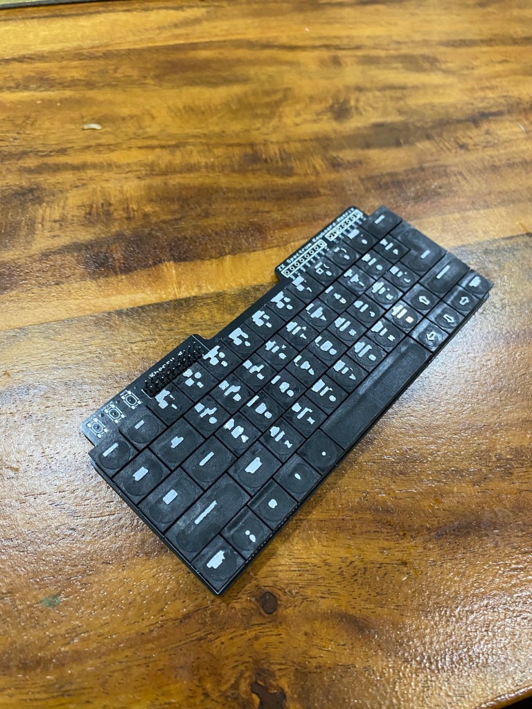
Yep, these are WORKING keyboards for the
The A500 Mini Amiga
The C64 Mini Commodore 64
And
The Spectrum Next Mini (an Xberry Pi case) which is a 50% X &Y (100% Z) scale next mini styled case.
*any colour available as long as it’s beigey brown
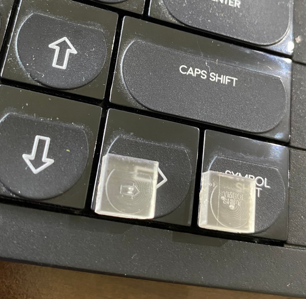
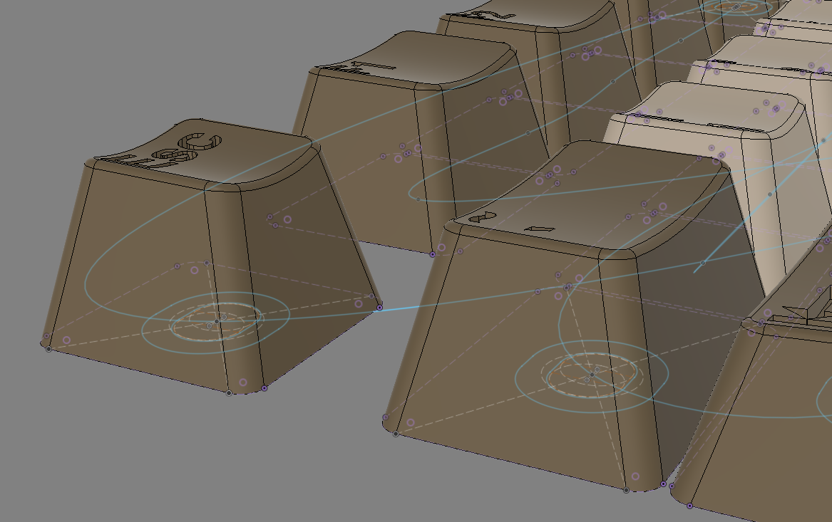
Have spent the last week tweaking, adjusting…probably too much really. Likely i’m actually procrastinating about making this thing physical. The new stems and locking mechanisms are are all aligned and merged in with the keycaps!
There really ain’t too much left now on the keycaps. Some minor adjustments will be needed to the stem – It’s parametric – so I print, fit, adjust one parameter which changes all keycaps at the same time (unless something breaks) and re-print.
Have made final tweaks also to the main PCB – I’m on version 11 of revision 9 now!…Again, too many little tweaks here and there, I really must fire the printers up!
I’ve been tweaking away, adjusting the EDA (the PCB via EASYEDA) and the CAD (the keycaps via Fusion360)…There’s nearly 100 bits that need to line up for it to all go well.
Previously, with my C64mini kits design, i’ve broken out the vernier calipers , measured, tweaked, printed, measured, tweaked, printed…….until everything fits just right!
For the A500 Mini Amiga, the ‘about 43%’ scale means the keycaps are just too tiny to shove underneath my ‘go to’ 5.8mm x 5.8mm switches . In addition, soldering 60 odd switches, another 60 odd diodes, and the arduino is a tad arduous, so change was needed. I’ve jumped to Surface mount style components
One advantage of Surface mount – Machine assembly – I’ll be buying in the boards mostly populated!.
The machines that assemble the boards use a file called a ‘pick and place’ file. Essentially a CSV file with co-ordinates!.
I had a ‘play’ with that CSV file, imported it into excel and plotted the co-ordinates
That looks suspiciously like a keyboard!
Imported them into Fusion as a Spline – The control points are the exact centre of where the keycaps are!
I just needed to align a point with one i’d already ensured was perfect in the CAD….and
The ESC key is perfectly located….
The centre of the stem of every key is perfectly aligned with every spline control point….Which comes directly off the Pick and place data of the PCB!
By overlaying the co-ordinates used to place the switches on the CAD model, I can now be very assured that the stems are located within the keycaps correctly, which are located within the keyboard…
or, in otherwords, it should all align, and hardly any 3D printing fake PCBS / jigs, samples, reworks needed…
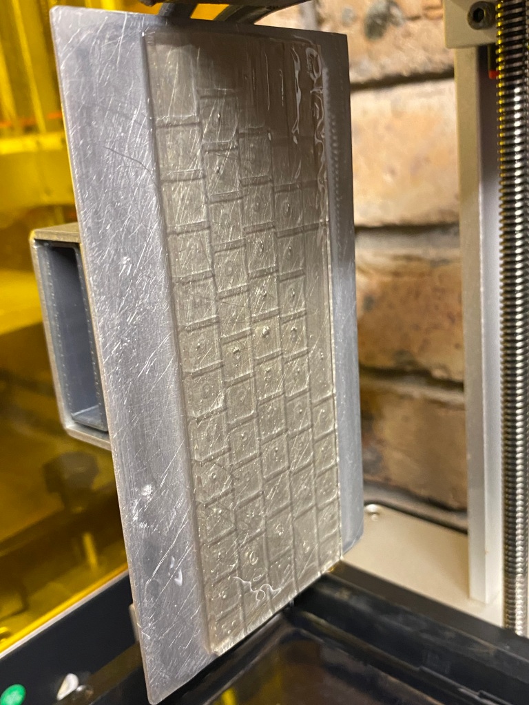
I’ve tonight finished routing the new PCB and switches!
A lot of work has gone into this! It’s got some ‘extras’ , it’s also an expensive board at 4 layers , 1.2mm thick and nearly 100 switches!
I’ll get to designing the other 2 or 3 (maybe even 4!) PCB’s needed for the complete setup, then place a single order for them all, so it’ll be a few weeks till I can test this beast out!
If they work, Ill make few ‘special limited edition’ early ones to send out, I’ll not spoil the surprise extra features till they’re in my hands!
Well, that’s a wrap for idea 1 – concept was ok enough, but…it’s no-where near good enough for a production run.
After half a dozen trial prints and practice fittings, I’m heading down another path.
The Many faults include
Keys fitting poorly to switches.
Keys not fitting on switches straight
Keys just not fitting onto switches at all
The attached picture sums it up really.
All is not lost however. This is something I had to trial, if it worked, it would have been cheaper and awesome.
I have a few ideas up my sleeve…My next option is right now, considerably more expensive, but has been underway for a few weeks now, I’ll reveal a bit more once the process is done.
On the plus side, the keycaps look great in Amiga Beige! – I’ll work on the darker caps another time.
The PCB layout works great, firmware works, so, really, it’s down to the thing that always was going to be an issue, the switches!
First working keyboard keycaps are off the printer! Only this bit to show as most of the print failed 😛
Well,, 3 prints failed, I’m trying to learn how to use my Photon Mono-X, so far mostly unsuccessfully, these were printed using a known good combination of Photon Mono and Commodore Brown resin 🙂 ….and still it partly failed!!
Next, I have to optimise the design for printing. I’d added some features to make them work better, but, those features don’t translate to printing very well, D’oh! (That’s called not doing Design For Manufacture!).
Resin printing can be a hard beast to tame, especially when printing 94/98 individual items (98 if I can two keyboard types!!)
This first print is literally an ‘auto supports, Jab a few extras on, hope for the best’ quick test to prove the mechanics. When the design is finished, I’ll need to spend a couple of solid DAYS (maybe a weeks worth of evenings) adding thousands of supports MANUALLY to ensure every keycap comes off the print perfect!
That sounds a lot, but printing a single item is different than printing the same item hundreds of times, so it’s really worth the up front investment in time.
And, speaking of time, I’ve just clocked about 600 hours evenings and weekends, on this project now 😛
I’m rather happy otherwise, next week, I should have a full working keybaord to demonstrate 🙂
Quite a lot of progress, but it doesn’t look like a lot of progress.
Firstly, I’ve had to re-do most of the keyboard CAD – I simply didn’t like the ‘blocky’ effect of the wider topped keycaps I’d created – as you can see below they look a lot more square in real life than they did in CAD…
I’ve now clocked well over 200 hours developing this set of keycaps, likley there’s going to be tens more tweaking / optimising!
So, along with the less blocky (more slopey) keys, I’d discovered my workflow in CAD had created tapered keys – the tops when viewed from above look like parallelograms, wheras the original Amiga had more square keys – it was quite a lot of work to alter this – see the parts below by the red arrows – the bottom bit is in towards the middle more than the top bit.
Progress to date has been surprisingly quick – most of the ‘easy’ stuff is now done and I’ve added some extra functionality. Most of the research is now done – have spent waaaaay too long googling connectors, Pogo pins and component types / dimensions.
First print of the keyboard PCB and CAD fitout – pretty close
My workflow generally is to eyeball, sketch, measure, adjust….Then when it’s close enough, i’ll print on paper, adjust in CAD, print again then………3D print
a 3D printed space sample
I’m quite chuffed – the first 3D print seems to fit reasonably well! – there’s some adjustments needed, mainly the top of the keycaps are a little too wide, but overall for a first run, not bad.
The PCB outline
To work out a PCB outline, I’ve scanned the A500 Mini on a flatbed scanner and trace around the important parts, measuring many with calipers
the Keycap CADAnother view – the big circles are the curves / slight indents in the top of the kecaysThe CAD compared to a scan of the actual A500 Mini
Before I 3D printed the sample, I put the A500Mini on a flatbed scanner to match up the holes – as you can see, it’s pretty darn close! – you’re seeing a canvas underneath the actual CAD model of the keycaps in Fusion. The Enter key is black as i’d discovered a slight profile error, so spent half hour correcting a 0.2mm height error 😛
But, wait, there’s TWO
During the design phase, there’s a process of discovery. My main discovery for the A500Mini keyboard was that….I’d possibly need TWO PCB’s!!
If you look above at the underside of the keyboard you’ll see that there’s no space on the top for electronic components! The PCB needs to mount entirely flush to the case of the Mini. This means I’d need a PCB assembly service that can handle double sided boards (a possibility) – And to also consider a two PCB solution. There’s cost and ease of install considerations for both ways.
The A500Mini has a number of test points on the back, I think using Pogo Pins I can maybe make a clip-on PCB that can securely tap off the USB test points, meaning, a solderless install! – hence the upper white PCB that sits in place of the A500 PCB above
And, now I believe I’m going to go with a THREE PCB solution…….because…
the one with the holes in sits above the stock PCB
That’s a scale floppy disc! with a Micro SD card inquick render of the floppy slot in the case
I figured I’d go one better and make a REAL fake floppy disc. and, the best thing, after several solid days of research and CAD testing, I believe it can work 🙂 – it’ll only need two small cuts inside the A500 case and be totally stock outside. there’s a little more tweaking needed for the floppy disc design to make the MicroSD slot more elegant . I’ve ordered a whole bunch of parts to physically trial this and see if it’s viable.
So, Summary. Still a long way to go, the Keyboard itself is the priority here, the ‘floppy disc’ is just a whimsy on my part for the time being, its development is secondary and may not even make it to a real release if it’s not robust enough.
Keycap CAD – Cosmetics finished, Just needs the ‘switch’ solution figured out
Main PCB – Outline finished, needs routing, quick job to finish
Not much of an update, just a couple of pictures to show i’m still slowly tinkering.
The keys do seem much easier to model as they’re less curvy. there’s only a top ‘dip’ in one plane which is easily extruded into the keys using circles that are varying radius’s to give a 0.9mm ‘dip’ in the top of the key. that dip will be much less prominent when the whole thing is shrunk 50%, but I like to try to be reasonably accurate.
First Proper scale PCB layout for the A500 Mini. it mostly looks like it’ll work – BUT, there’s some problems.
I’ve highlighted the problematic switches with white blocks
The Problem – Having switches at 0 degrees or 90 degrees means at some point, due to the staggered keyboard, some will overlap. I’ve spent a few hours optimising the rotation of the switches to reduce the number of overlaps to a minimum, AND, to give all those overlaps a common ‘thing’ that possibly provides one way of easily fixing this.
Zoomed in view
I’ve made it so that Every ‘overlapping’ switch has the bottom left pad causing the overlap. This means, with the right switch type, I can simply cut off this leg for each of the 8 problematic switches and have the keyboard work just fine!
In Most SMT switches this size, there’s 4 legs, but often only 2 are used, (single pole) or sometimes there’s 2 separate switches inside (double pole). provided I use the correct two pins, they should just work fine with 3 legs soldered in. This isn’t exactly an industrially abused keyboard, so 3 legs is plenty of mechanical support.
BUT – I’m unsure if I could ever convince a PCB assembly house to cut a leg off the switches and solder them at a reasonable price, meaning that I may need to solder these 8 manually myself.
There’s a potential other fix also – Rotating the switches at ‘odd’ angles!
If you squint closely, there’s now no overlapping pads on the switches, However, this comes with potential issues
1 – Manufacturing, companies may not want, or be able to put switches on the PCB at arbitary angles like this
2 -Available space within the A500 Mini is currently unknown, which may not give me enough height to be able to do this.
Physically, a 6mm switch, placed at 45 degrees ‘just’ fits within the available 9mm envelope for each 50% scale switch
Rotate that square and you get a circle – which is less than 9mm, which is less than the keycap size!
What this means –
If I rotate the switch, I will not be able to have a recess on the keycaps. On the C64Mini, to keep the keyboard profile height correct, the switches sit about 1.5mm into the keycaps when pressed down. Without this recess, the new keys may need to sit higher than they should. But, this depends on how much space is available underneath the fake keyboard in the mini – it should be possible to add some spacers in to bring the height back down.
The switches sit inside the keycap on the C64Mini keyboard kit
So, The big summary is, Right now, there’s no roadblocks to making this work. a Fully automated production is preferable to bring costs down, so i’ll keep working down that route.
Things to do –
Contact PCB manufacturers to figure out manufacturability
Minor update! – Slowly working on the PCB design for the Amiga Mini – I’m tempted to actually produce a few of these as a Beta run so I can get ahead on the keyboard matrix programming.
I’ve priced up on https://jlcpcb.com/parts/ a BOM to build a minimalist Pi pico so that I can place one directly on the keyboard – and surprise, just like the Arduino Pro Micro device – The sum of the components is more expensive than the price of a full Pi Pico ! BUT, and key point, it’s not all that much more. building Arduinos out of components were typically around DOUBLE the cost. The Pi Pico isn’t!.
However, adding a RP2040 discreet chip to my PCB adds a small level of additional complexity to the board and puts me at risk of parts going out of stock so it’ll be a weigh up when the real Amiga mini is released – If there’s enough space on-board to make a 2 layer board, I may well do this. If not – well, that’s what the TWO circuit boards above are.
Early days yet, but first look suggests that the above would be only marginally cheaper (almost not worth it) than putting a discreet pi pico on-board
oh, and of course, these will be fully populated boards! just add keycaps and ‘go’
1/2 scale Amiga Keyboard – the keys might just fit!Schematic with who knows how many errors 😛
Had a little play, using some SMT buttons i’m using in another project. These switches aren’t quite correct for this project – I need ‘square’ button-y bits and preferably ones with a small sticky-outy or inny bit that’ll let it capture a keycap straight.
Assuming the A500 Mini is 1/2 scale, like the C64Mini was then it’s looking good for keyboardification.
This keyboard is about 225mm x 56mm which is about 1/2 the size of the original membrane – I ‘think’ – based losely on numbers from here which says
Full sized Amiga is about 470mm wide by 325 deep.
Half that gives about 235 x 162. take a bit off the 235 for the case thickness bit – gives 225. then height is set roughly by the number of keys ‘down’ and eyeballing the various membranes i’ve found!
However – I don’t know the internal space availability of the A500 yet – so plan going forward for now is to prototype as a 2 part PCB.
One design part of the C64 Mini keyboard kit I never really liked is the standalone Arduino Pro Micro mounted on the rear due to being no space. Adding it to the main PCB was also out of the question as the separate components would have been at least double that of a ‘cheap’ arduino.
I’ll keep a 31 way (ish) connector on the main keyboard part, so it essentially acts like a traditional Amiga Keyboard. I’ll then have a ‘special’ RP2040 based PCB that converts the Amiga matrix into USB for the A500.
Very early days yet – But, this is the first start for making the Commodore Amiga Mini working keyboard kit! About 1/2 way done on the matrix, then the peripheral components to go.
Then i’ll ditch it all and start over as the above is a bit of a mess ;-P
I’m currently working on a design assuming I can use the same again. There’s very few switches on the market with a ‘square’ style centre part that can capture keycaps. I have leads on a few others, but plan this time is to find surface mount versions and try to get a batch ‘mass produced’ – i.e. little to no soldering needed for you lot!
Early days yet, it’s been quite hard to ‘get back into the grove’ . here’s hoping I get this finished in 2022!
Hi All. everyone that’s expressed interested has bought up a kit, thankyou all. I now have general stock of unassembled kits available for immediate shipping
Switches will be here in a day or two!, i’ll email everyone about kits shortly.
Purchased some ‘old gold’ pigment from https://www.resin8.co.uk/ and tried it with the keycaps for something different. Came out ‘ok’ – nice and gold on the top, but lacking in gold on the sides. I suspect the particles weren’t being agitated sufficiently and sank to the bottom.
I’ll try again soon with a higher concentration of pigment and see how that goes before considering offering these as a product!
The final hurdle for ‘good enough’ for me now is the space bar.
Every key prints lovely, except the largest one……Take a look
Eeeeew, kinda looks like a ….
I’ve gotten all the ‘hard stuff’ over and done with first, or so I thought. Life’s taught me to generally avoid going for the low hanging fruit first, save the easy stuff for later when you need a boost.
Well, no matter what i’ve done (so far) in 12 iterations, have I been able to get a good looking space bar.
Now this has become my sole focus and roadblock for a successful print
Turns out that this is a combination of quite a few variables, I’ll list a few and probably follow up another time with clicky links and research
Exposure times are wrong –
They could be , I’ve really just gone and shoved stuff in to print and hoped for the best with standard settings. I Have now tweaked up the settings a little bit to 2.2s per layer due to mixing pigment in, and have had no real failures. I’ve also increased the first layers exposure times to 30s, still seeing minor issues there
FEP tension is wrong
Not really, This is a brand new printer, i’ve had zero catastrophic failures and have been overly cautious monitoring (and catching) early delamination from the print bed issues – Three times now
Bad Resin
Possibly. I’ve 3 types (all anycubic) and seeing the same on all 3
Temperature
Possibly, lots of people have been reporting issues in cold climates, I use the printer in the conservatory and it’s sub 10 degrees C in there regularly
Low temperatures cause increased viscosity and warpage issues with fine features from the FEP pulling them through the thicker resin
MY FAVOURITE
Exposure –
Too low exposure times on fine edges cause resin to cure, but not as hard as it should. So, when the layer sets on the bed, when it’s pulled off the FEP, it warps as it’s soft. This, I believe is causing the sagging issues i’m seeing on that space bar – it’s printed upside down, so the supports hold the points up, and between the walls sag, like an electric line held between two pylons
My solution……
Probaly waaay too many supports, but this way, each ‘sag’ will be between supports that are just 1mm apart.
I’ve also nearly doubled the wall thickness to about 1.8mm – from 1mm
Blue lines show original thickness, gold shows it doubled
Hopefully now, this is the last step, Colour’s good, CAD is good, Supports are good.
I’ve ordered 2 Litres of clear resin ready to go and have a colour that’s not exact, but close and, importantly , very easy to re-create
Resin8 Earthy Brown, 3 ‘blobs’ of the end of a lollypop stick to 100ml of resin. and Black, 1 blob.
– The Rich brown used previously was too red. I’ll experiment a little with more black when running off the final tests
It’s taking ages to get progress on the 3D printed keycaps, I’m so close, but still have a few months of tweaking until I get it perfect enough to consider it a saleable item. watch this space 🙂
In the interim, I went and purchased a bunch of these
They’re a “100Pcs A28 Tactile Push Button Switch Cap 6*5.1mm Applies to 5.8*5.8 7*7 8*8 8.5*8.5 Self-Locking Switch Button Cap”
And, judge for yourself……
Old school!
Err.
Well, it’s more comfortable than nothing, and certainly opens up some options for unusual keyboards in the future 😛
yes, it’s not perfect, BUT for £1.68 you can have non painful pokey bits and actually do a reasonable job of typing on basic
or, splash out £3.36 and go for a dual colour like I did 😛
BONUS PRIZE TIME………………..[edit, grabbed by someone! ]
THE first person to order a kit and mention that they want these keycaps, I’ll chuck in a set of grey/black ones as pictured for nothing – I purchased enough to do properly do 2.5 keyboards, or 3 if you don’t mind a mix / match of black and grey!
Note, if you’re ordering your own keycaps off aliexpress, the internal dimension is key here, they fit, you can go a little smaller
the absolute maximum external dimension is 9mm, this leaves about 0.48mm clearance between keycaps.
Most people would say this was caused by an over excited person, whom, upon waking early and discovering the complete print decided to not follow the correct drying / washing procedures in order to get it finished quickly!
I, err, disagree…
Either way, I now have a firm grasp of changes needed to the CAD model and also the supports needed in the slicer.
Those changes are fairly substantial, so I expect it’ll be a little while for my next update, happy to document them also if anyone’s interested.
Freshly dried and washedPerfect sizeA quick comparison
It’s going to be a while yet, but I’ve finally fixed some long standing issues with the keyboard model i’ve been building in Fusion360
Doesn’t look like much!?
The main issue was a badly created model!. I’ve junked quite a lot and started back prior to when some odd dependencies crept in and really put some roadblocks on scaling things correctly and adding finishing touches.
But, it’s been worth it
That previous picture is the underside of the Keyboard – Those holes in the keys are 2.2 x 2.8 holes. it’s a first run at fitting the key switches into the keycaps. a lot more iteration needed to hollow it out a little and create some form of inbuilt snap-fit with stress relief, but…it’s a start!
The silver / grey keys over on the left are the ‘parent’ keys
If I make an update to the curves or size of a parent key – it rolls out to all the same sized keys in its row
if I need to iterate the hole size for the key switches, I simply change a few parameters for the hole size and it rolls out to all the keys in one go.
I’ve taken so long to develop it parametrically as it’ll now be so much quicker to iterate
Lots of parameters to change!
and, here’s a new render!……..going to spend the next few weeks iterating, and hopefully over Christmas , fire up the resin 3D printer for the first time!