
A repeatable two colour resin print.
Dialling in variables, this is now the 4th attempt and each time it’s getting better 🙂 (other than the first time which some keys looked great on the other printer!)

A repeatable two colour resin print.
Dialling in variables, this is now the 4th attempt and each time it’s getting better 🙂 (other than the first time which some keys looked great on the other printer!)
It’s been a couple of weeks of iteration and maybe ten actual prints between these two prints!
In person, the difference is very notable. more subtle in pictures.
This is as good as it gets for a standard set of keycaps 🙂 I’m finally happy.
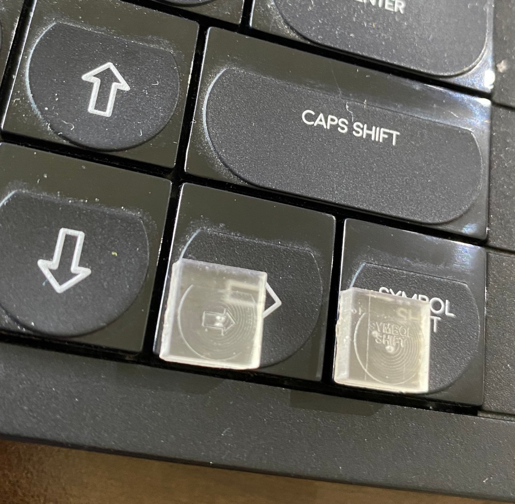
Now I can really get stuck into experimenting with getting those legends white! I have three ideas, one may be limited somewhat by the viscosity of water!


Ok, had a brainwave.
Too early to say if this is practical for production but it’s certainly worth a few weeks of experimenting 🙂
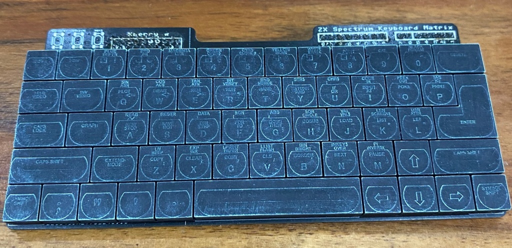
Could hardly make out the keycap legends whilst testing and sorting some bugs in the matrix.
Figured a quick bit of Dry brushing might make the words pop a little!
I’m gonna do my own personal next Mini just like this 🙂

I’m going to write to those Fox’s Glacier Mints people and suggest they make tasty keycaps!
After two days of hunting, Found a paint scraper to remove the keycaps off the printer !
Also Bought some IPA to clean the keycaps up…
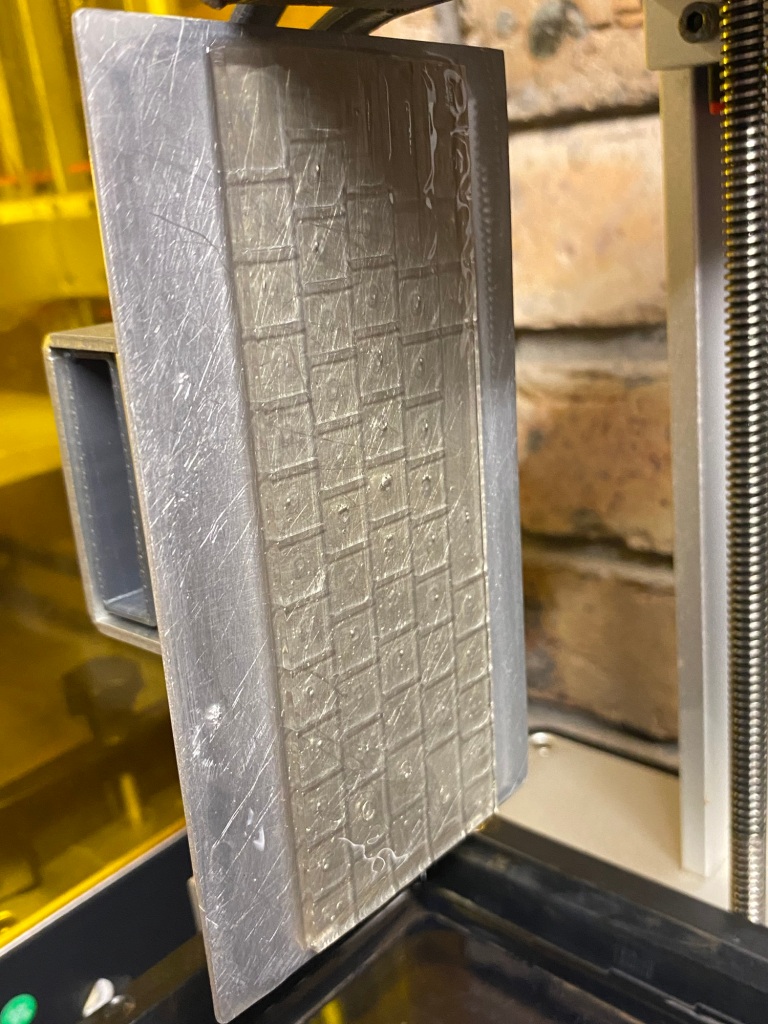
But…I’d forgot to actually prepare the slicer properly for printing.
I’d planned to just print straight on the bed without supports.
I forgot to remove the first base layers / brim / whatever it’s called so there’s no hole on the underside of the keycaps!
Ah well!
I’ll re-slice and reprint tonight, it’s an hour to print, so very quick to iterate!
Also, can’t find my curing station, and it’s raining today…d’oh!

But, forgot to buy IPA to clean the thing off once printed.
Found a Very well priced 5L of 100% IPA at Sydney Solvents for $35 delivered!
Now, if in a rush, I could pay $10 for 125ML at Bunnings
Or even a more reasonable 250Ml for $14 at Jaycar
(They even have 5L for $76!!)
But, I’m stingy, anticipate that I’ll need quite a bit (even though it took me two years to not use 5L back in the UK due to fastidious recycling)
So, summary, I’ll
Be printing key caps next week at the latest!
Then I’ll re-do the Next mini PCB a little bit too!
Heavy on the Photos this post is….
Last year, I needed to scratch an itch…so I spent over a thousand hours developing something

Had to admit, the failure of the Beta 9 got to me a little bit. Took me a couple of days to take stock, stand back and think.
After much thinking, about life, being married, kids and generally having to work hard at a day job, remembering about that one time where that bloke ripped you off, Postulating how things can build up and get to you to the point where you just think that getting screwed and having your balls in a vice would be more preferable………..
You can come to yet another epiphany!….Screw it and put the Balls, in a vice.
I present to you……..The precursor to the release candidate for the production version….Err
Continue reading “Super LED Blinkenator 2000 – Scrrew it.”
Some minor changes to this PCB
Balls – The PCB flexed waay too much to make a decent contact
Continue reading “Super LED Blinkenator 2000 – Beta 9 incoming”Back a few years ago, I ventured into making my first PCB in over 2 decades. it was motherboard to hold a raspberry pi zero, and fit within a zx spectrum case.
it was inspired a little by an article in MAGPI magazine by a Mr P J evans.
I did kind of goof it up a bit, so relegated that to the ‘ideas to do in the future’ drawer
Whilst perusing Kickstarter today, I found this –
https://www.kickstarter.com/projects/hermitretro/hermit-retro-zx-spectrum-board?ref=thanks-copy
A custom board for original and reproduction ZX Spectrum cases powered by a Raspberry Pi Zero and the Fuse emulator

So I backed it!
Have a look 🙂
it’s a far more elegant solution than I came up with.

Been a busy few weeks here at Bleugh.Biz industries, working ridiculous hours at my day job, keeping kids from murdering each other during the evenings……But, i’ve been getting some good tinkering time in.

Some very good progress has been made! – and this is the board that’ll hopefully, finally, once and forever physically fit perfectly
Some Notable changes
I’m sure there’s a few more changes i’ve missed, but that’s the important stuff.
Where from here……….IF this last board plugs in, fits well, i’ll be sending out to the key Dev team. I can then kick back, relax a little and start again playing with the software side of things, Both Next side and Arduino side!.
I’ll eventually also need to consider switching over the whole board to SMT, or as much as possible. I’m not that daunted by this as there’s quite a number of ways this can be achieved, including just putting the 32U4 straight on-board, or considering changing the micro type entirely. After all, the main reason i’m using a 32u4 is that it’s cheap, Arduino compatible, has USB built in. All those things give a great ‘dev board’ capability that people can use to simply plug in and tweak!

I’m going to be reserved till it actually works…….But, I really think this could actually work
Continue reading “Super LED Blinkenator 2000 and that J15…An epiphany?”Firstly, D’oh!
now that’s out of the way – have a nose


With a successful 2nd Kickstarter – The Spectrum Next will have between 8,000 and 9,000 users.
Lets Dream a little and imagine a Bright world where all the users have a Super LED Blinkenator 2000 installed….
9000 users = nearly 40,000 inserts to be made!.
lets say just 10% want the blinkenator, I still have to make nearly 1000 of the things.
I’ve been researching a little and identifying bottlenecks to SUCCESSFULLY produce and deliver my board in those quantities
There’s some scary numbers!
So, I’m now pressing forward with TWO designs. one design, the one you’re all familiar with, suitable for small time production in small batches here and there on my weekends, only ever endeavouring to sell maybe a 150 units ever
and the second, a ‘mass produced’ item that requires minimal ‘hands on’ time from me to deliver, but will require some significant outlay up front.
The pictures above are a first run result of my Design For Manufacture for the inserts….A different injection mould, possibly 2 parts, maybe 1 and using a flexible PCB!
some key notes……..
Advantage – no connector soldering needed on my part – currently I’m soldering 16 cheap ‘bridges’ to each main board. with this insert, someone will be soldering 8 SMT FPC style connectors
Advantage – it’s likely that this design will be easier to make ‘injection moulding’ manufacturable. the existing design is tricky, but not impossible
Advantage – FPC connectors are a bit more reliable and easier to use than my bridges for the end user
Advantage – FPC / flexible PCB ‘legs’ on the inserts will mean a little bit easier installation by the end user
Advantage – Uniformity of Light – This type of construction allows for a much thicker ‘top layer’ – which will diffuse the light far more. Also, more of the insert will be better lit up ‘from below’ rather than from the side that i’m currently doing.
Disadvantage – FPC connectors are more expensive
Disadvantage – Flexible PCB’s are more fragile
Disadvantage – Flexible PCB’s are more expensive than FR4 for small quantities, so prototyping ability is very limited. at The quantities I need though, there’s not that much difference
There’s more i’m sure, once the final numbers are ready, I can see if a kickstarter makes sense, it may not be financially viable if the whole thing needs to be sold at £80 each……
if I can get closer to that £50 mark, then who knows!

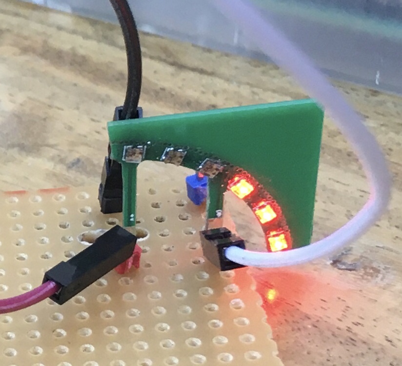
The inserts arrived – and they look fantastic
I hand soldered them using 2 year expired solder paste and a hot air gun
Continue reading “Spectrum Next Light strips – more! – FIRST LIGHT”

Had a little bit of a play with the daughterboard to see if there’s any possibility of putting a ‘push push’ SD card inside…
Unfortunately it isn’t without chopping at a couple of supports inside. I’m trying to keep my Next case fairly minty – untill it’s possible to get another, i’m going to avoid this mod.


The reasons it won’t fit – The case was designed with two ‘helper’ guide rails for the SD card – shown in yellow in the images above. Those rails stop any push-push mechanisms from working – there’s just not enough mounting depth for the card reader.
Now, if someone were prepared to snip those rails off….then it’s entirely possible to knock up a new daughterboard……I’ve already done most of the EDA before I thought to take the next apart and check 🙂
A little something different as I work up to posting some new content after the summer hols….
If you’ve ever owned one of the 8 bit computers of the 80’s and early 90’s, this is a MUST purchase magazine…
I’ts focus is the ZX Sinclair Spectrum (AKA the speccy / rubber beermat) and last years 2017 annual was fantastic
For an absolute steal of just 15 quid, hardback!
If your significant other (or yourself) has reminisced about days gone by…or wants to see what’s happening in the scene today, get this!
https://www.kickstarter.com/projects/47744432/crash-annual-2019-issue-100/widget/card.html?v=2“>https://www.kickstarter.com/projects/47744432/crash-annual-2019-issue-100/widget/card.html?v=2
https://www.kickstarter.com/projects/47744432/crash-annual-2019-issue-100/
