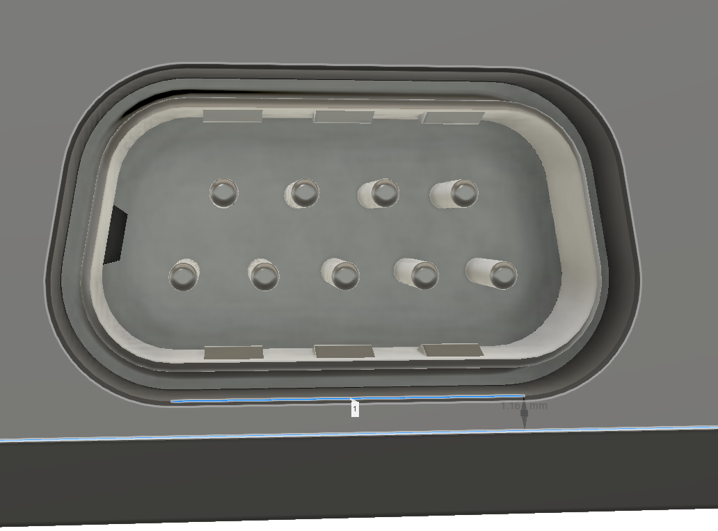
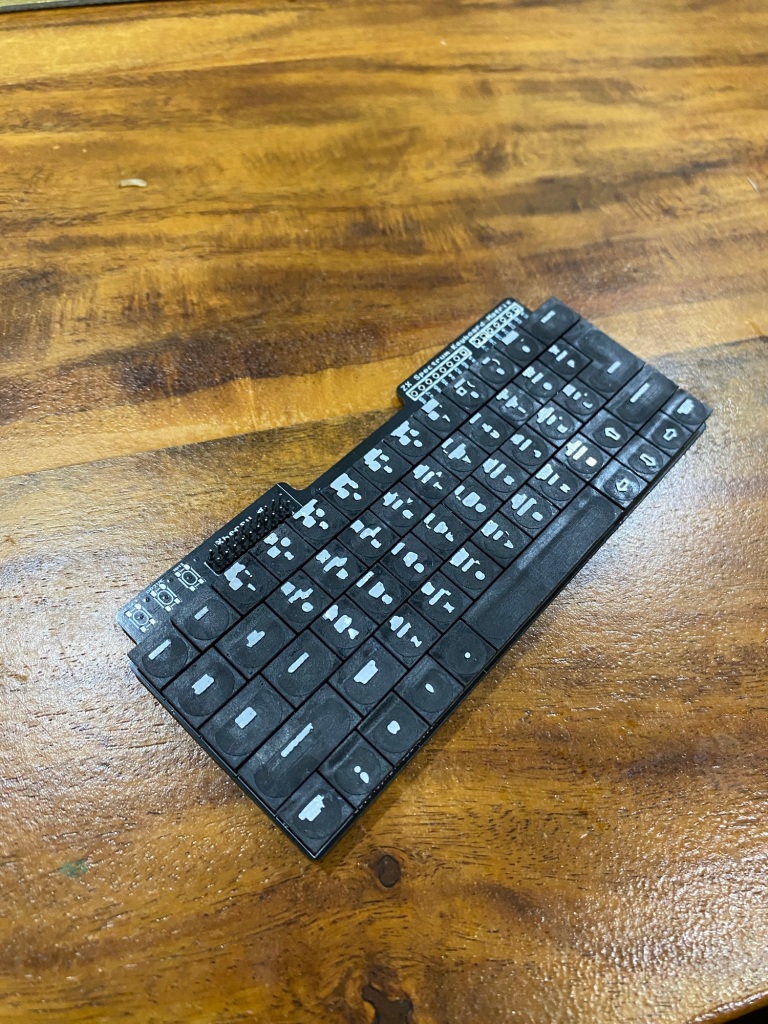
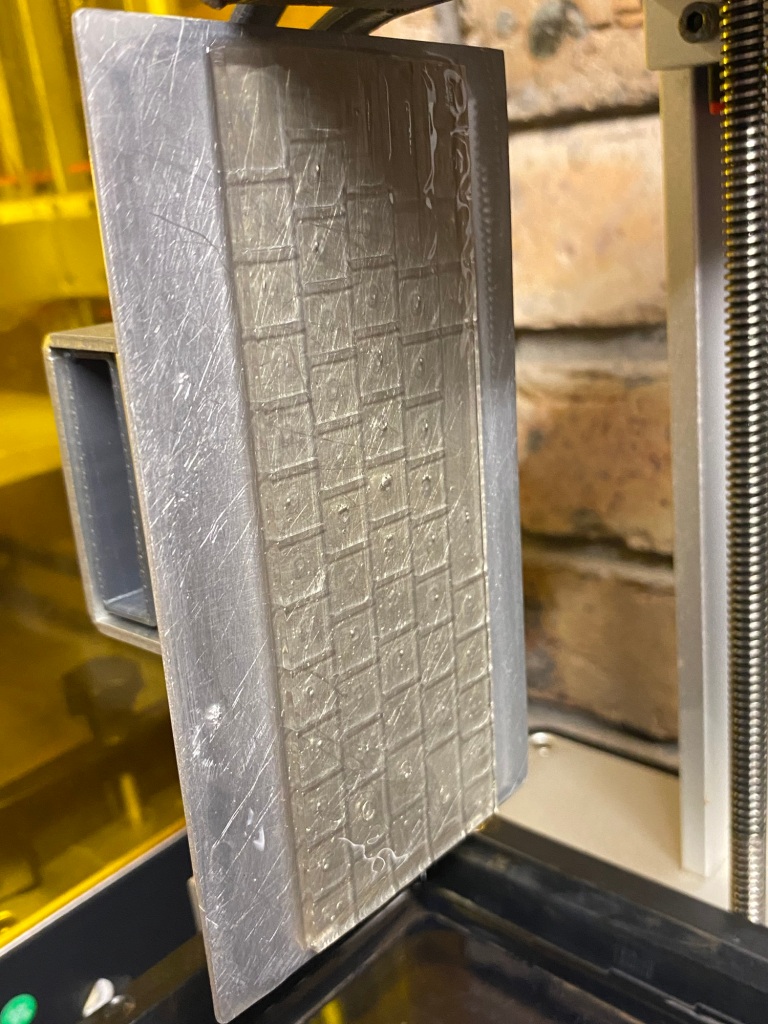
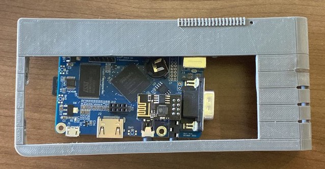
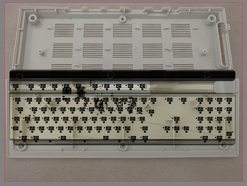
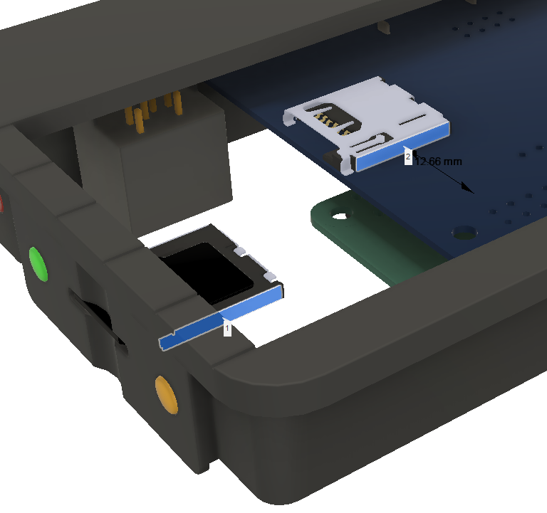
The Xberry pi’s SD card slot location isn’t ideal when putting inside a Scale Next Mini.
With the HDMI, EAR and power sockets all aligned to the back of the case, the micro SD slot sits about 13mm too close to the rear from where the ideal location would be on the side of the Next. – As can be seen below
It also sits about 30-35mm too far from the side of the case. So, an adaptor is needed. You can buy these ‘micro Sd / TF extenders’ – But, none in just the right length (they’re close), nor in a slight offsetty-typey thingy.
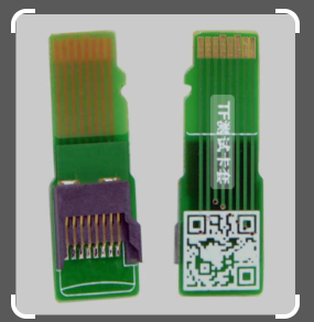
‘off the shelf’ Micro SD extenders
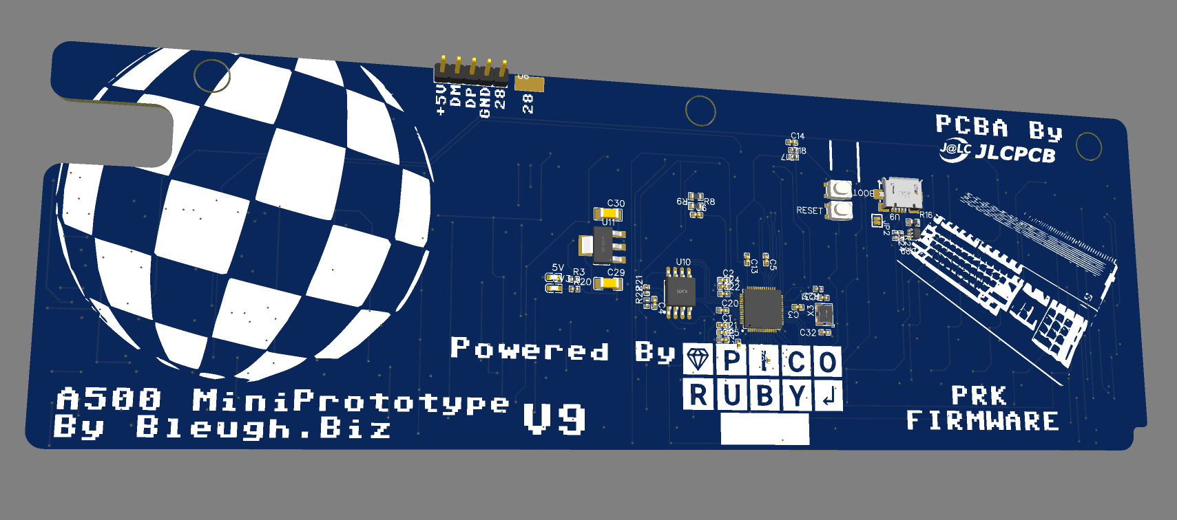
So, i’ve had to knock up yet another PCB!
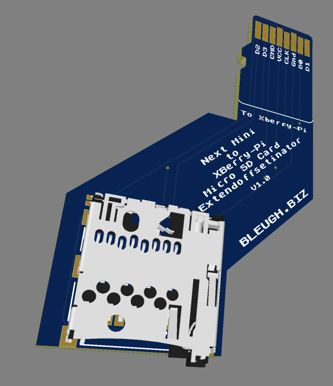
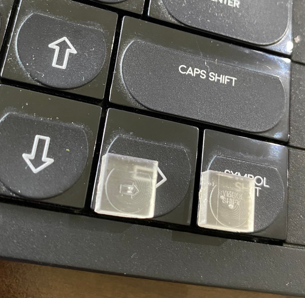
Presenting the SD card offsetor thingymajig.
Turns out there’s a few projects online that use 0.6mm thick or 0.8mm thick PCB’s to plug into a standard slot and extend out TF / Micro Sd cards. Micro Sd cards are 0.7mm thick though, and few ‘cheap’ PCB places seem to do that thickness…
I’m going to try both and see what happens. Seems most have success with 0.8mm.
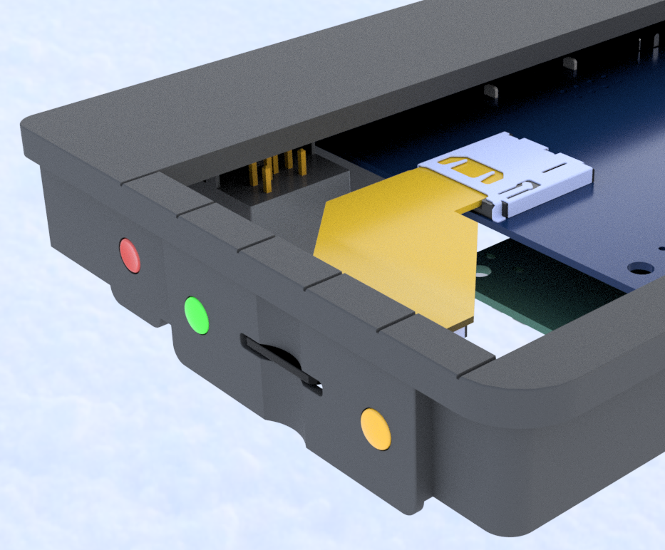
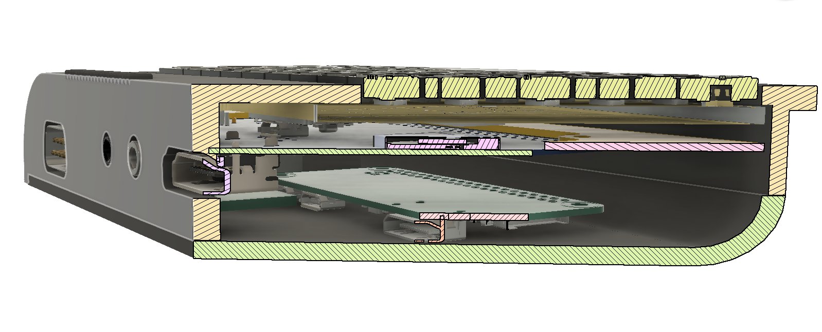
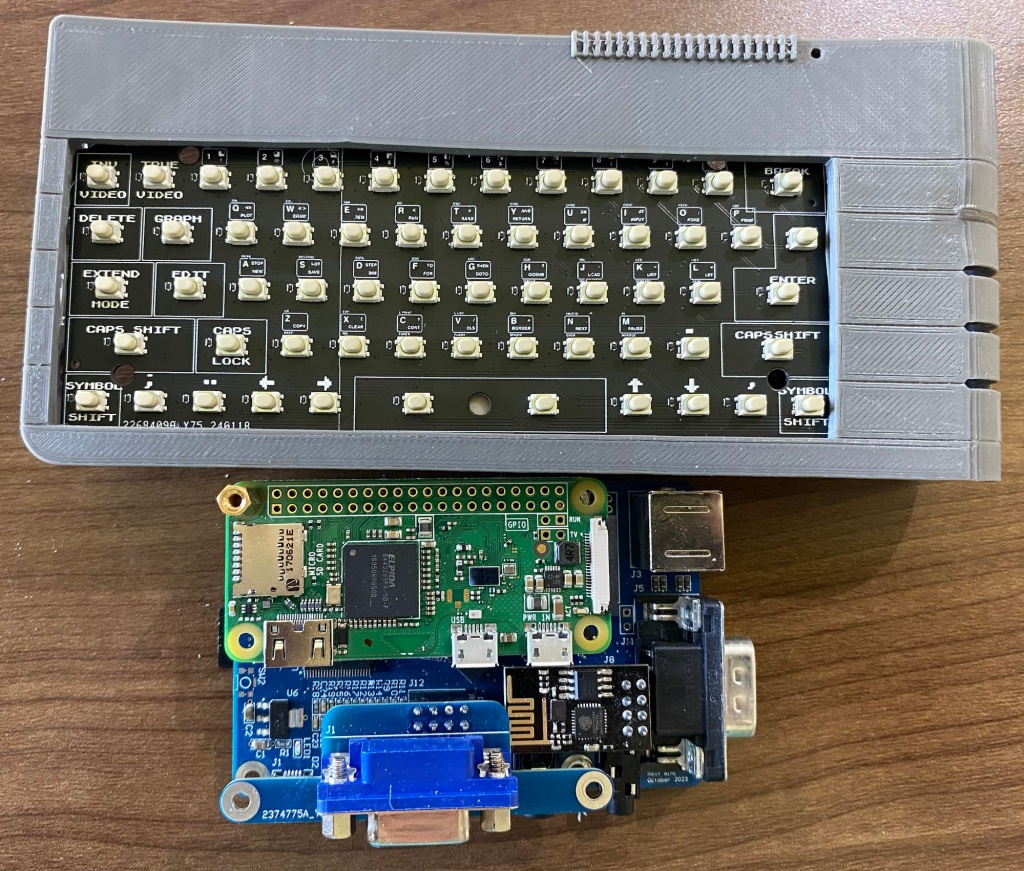
And, here’s the board sitting inside the Next Mini!
I suspect this board may change in size a little as it’s probably going to be easy to re-purpose it also for the 3 side buttons.
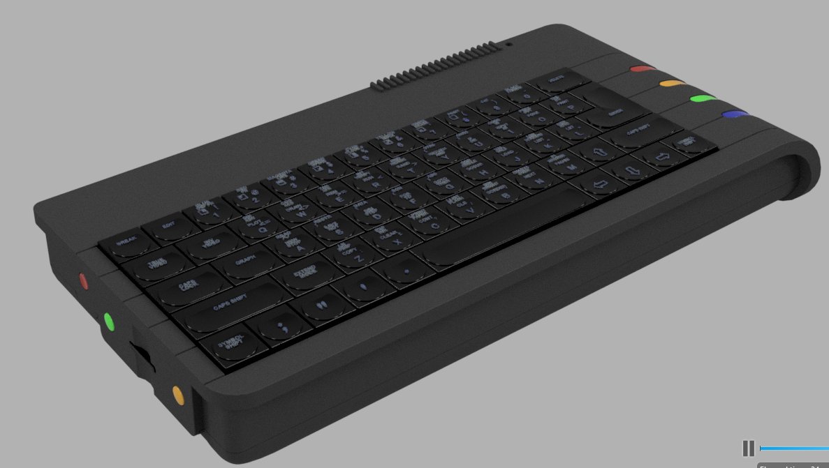
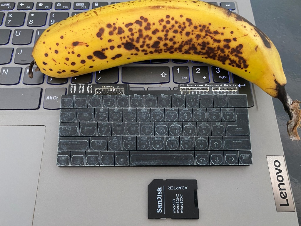
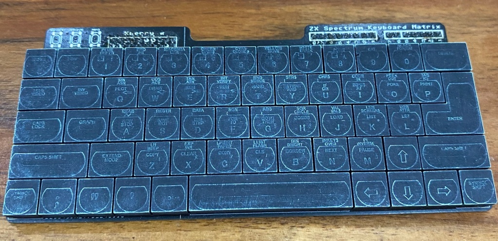
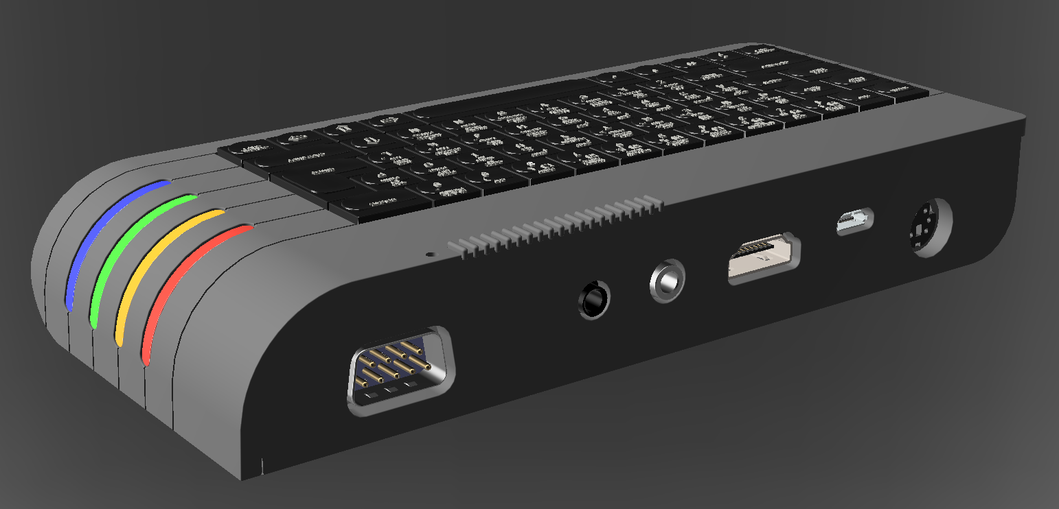
And, before you ask, Yep, all this is so that the Next Mini looks very close to the original, I think I’m close!


The reason my one looks ‘stumpy’ is that it’s exactly 50% of the length and width of the Next, but is exactly the same height!