Another un-interrupted few hours of Laptop time and I’ve now gotten to the point where….All the stuff fits. Now it’s just small tweaks, printing and ‘production’ .
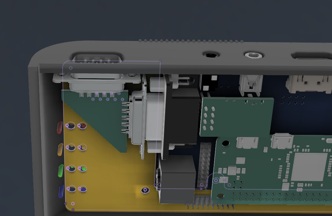
To get the PS/2 from the XBerry pi to the correct place on the rear of the case, I’ve put a small 6 pole ‘helper’ header over on the left.
Much Improved PS2 Port location – you can see the connector inside is now moved up and in-line with the other things!
I’ll then use just the small insert connector pins bit of the PS/2 connector and hand solder some wires for the first run. I might then make a fancy PCB for a final ‘final’ version
I’ve also now added a PS/2 port to the ‘rear’ of the keyboard PCB to save having a 4th custom PCB. For those that want ‘just a keyboard’ i’ll not be populating the rear side components (other than the Pi pico)
I’m now happy enough to pretty much freeze any problem solving, everything’s been solved now, so it’s down to relatively minor clearance and fitting tests now!
I’ll no doubt] need a few small revisions anyway and I’m really itching right now to make this thing Physical so soon, i’ll start using the 3D printers again, and be able to start back on the A500/ C64 and Blinkenator development!
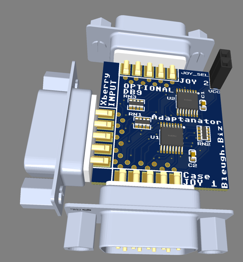
Mr Dom Superfro knocked up a schematic to allow two joysticks to be used on the Xberry-Pi. I’ve thus tweaked my small triangular Adaptinator PCB to be more rectangular and having ‘stuff’ on it
The Thing is tiny. I’ll work on a 3D printed shell for it also to be used with non cased X-Berry Pi’s!
Lots of house rennovations, busy at work, hoping to get some tinkering time in May!
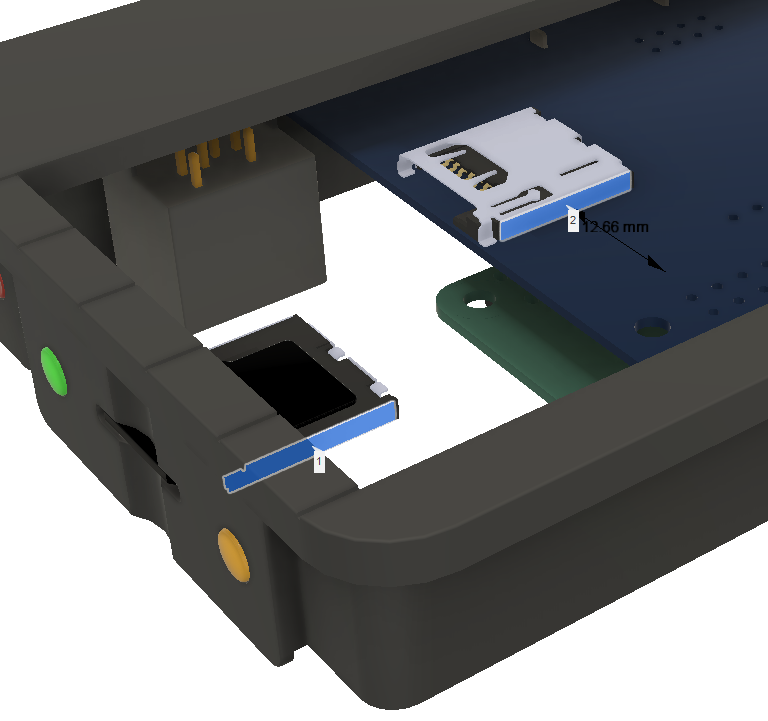
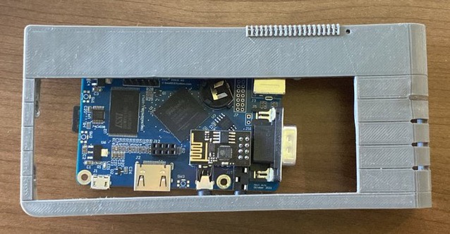
The Xberry pi’s SD card slot location isn’t ideal when putting inside a Scale Next Mini.
With the HDMI, EAR and power sockets all aligned to the back of the case, the micro SD slot sits about 13mm too close to the rear from where the ideal location would be on the side of the Next. – As can be seen below
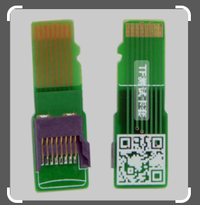
It also sits about 30-35mm too far from the side of the case. So, an adaptor is needed. You can buy these ‘micro Sd / TF extenders’ – But, none in just the right length (they’re close), nor in a slight offsetty-typey thingy.
‘off the shelf’ Micro SD extenders
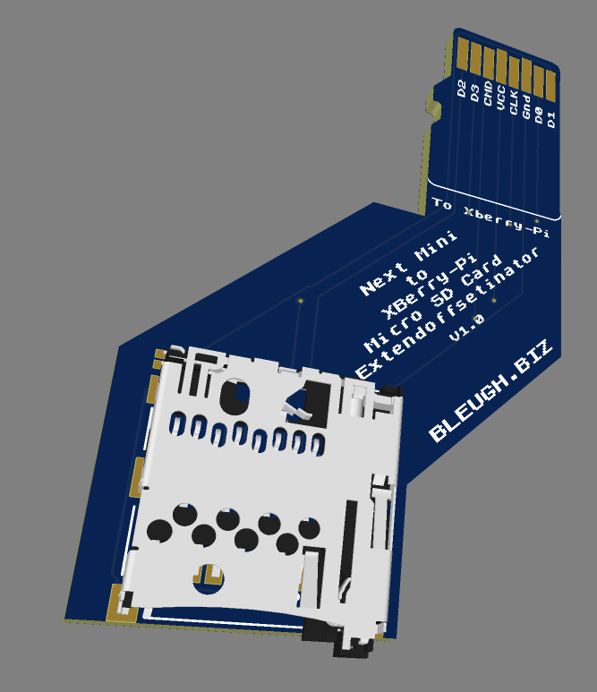
So, i’ve had to knock up yet another PCB!
Presenting the SD card offsetor thingymajig.
Turns out there’s a few projects online that use 0.6mm thick or 0.8mm thick PCB’s to plug into a standard slot and extend out TF / Micro Sd cards. Micro Sd cards are 0.7mm thick though, and few ‘cheap’ PCB places seem to do that thickness…
I’m going to try both and see what happens. Seems most have success with 0.8mm.
And, here’s the board sitting inside the Next Mini!
I suspect this board may change in size a little as it’s probably going to be easy to re-purpose it also for the 3 side buttons.
And, before you ask, Yep, all this is so that the Next Mini looks very close to the original, I think I’m close!
The reason my one looks ‘stumpy’ is that it’s exactly 50% of the length and width of the Next, but is exactly the same height!
Had some issues fitting everything inside the Next Mini case…I’ve almost wanted to dump the exactly 50% scale idea…
The Problem – Commercial DB9 connectors are cheap and plentiful
They’re just simple joystick connectors after all..many 80’s and 90’s consoles / computers used them.
Here’s a quick preview of one of my browser windows after spending a good 4 hours hunting for ones I specifically need
The Xberry Pi just doesn’t fit very easily into a 50% Scale Next mini case without some jiggery pokery. I want the case to be easy to remove from the Xberry so this means no mods. It was practically impossible to find suitable connectors to mount on my interposer PCB. I needed slim, not sticking out too far and right angled PCB mount.
I found a few , but even their footprints clashed a little and it left the joystick connector just a bit too close to the coloured strips edge of the case…….
BUT, a quick brainwave – Do as i did with the C64-Mini!, mount solder bucket joystick ports on the edge of the PCB……
Voila
And, here’s where it sits in the grand scheme of things!
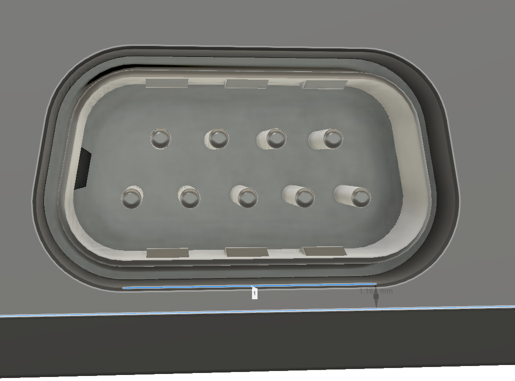
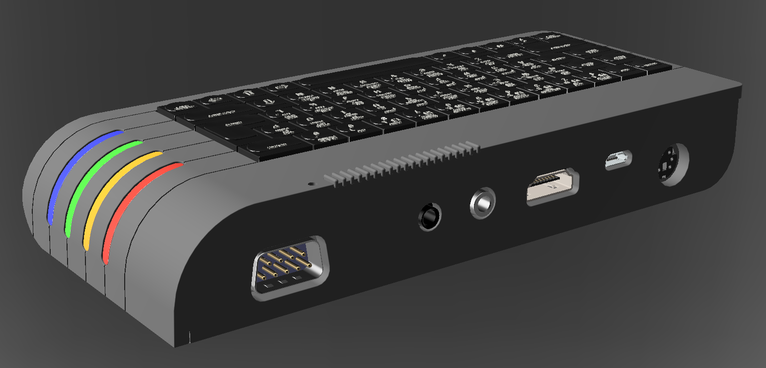
Here’s a render of the rear of the case
I’ve spotted that some Design For Manufacture will be needed on the rear of the case as the thickness below the DB9 is just over 1mm. The PS/2 port isn’t much more, so i’ll probably need to cut out the bottom of the cutout and put it on the bottom of the case. might leave an ugly seam if I get it wrong, but we’ll see.
Now, to tackle the PS/2 Connector and power LED. The Keyboard connector is proving problematic also due to lack of space, may have to get creative with yet another custom PCB!
Had chance to spend some quality time with my loved ones The computer. Have started on the final stages of getting the Next Mini ready.
Needed to finesse the keyboard design a little to allow for better fitting inside the Next mini. Have been mindful that it’s also designed to be standalone so the PCB isn’t an ‘odd’ custom shape like my previous iterations were and can be easily sit inside a standard rectangular case if need be.
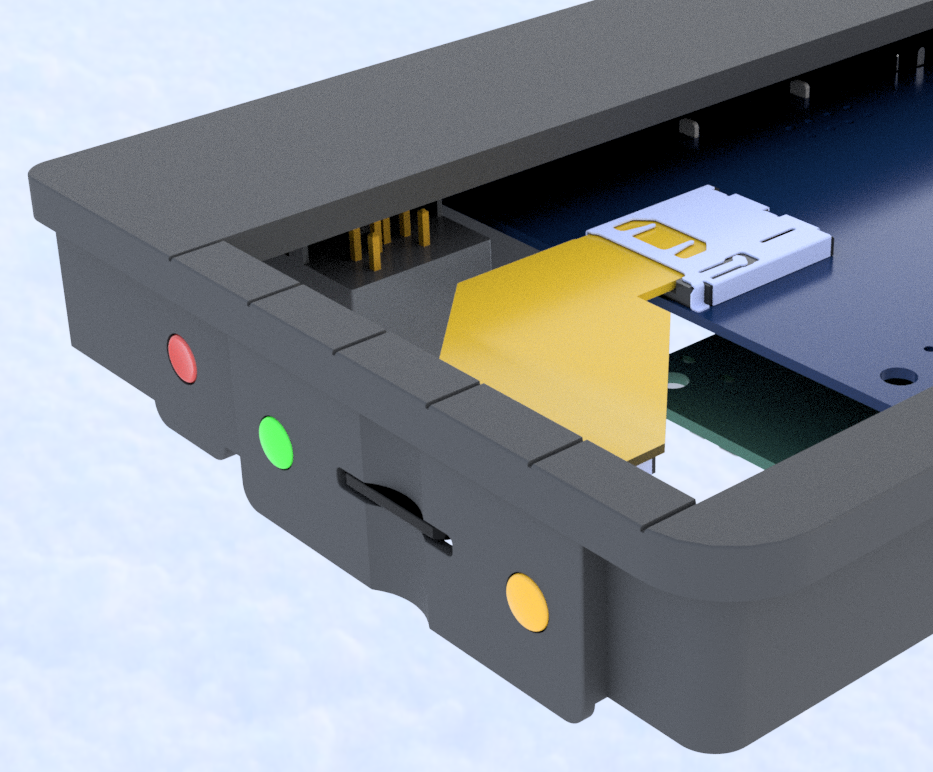
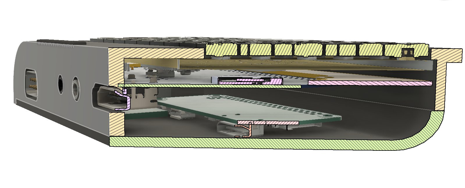
Have designed a Middle board (in yellow in the images) to accommodate the PS2 (keyboard / mouse), DB9 (Joystick) , Power LED, Micro SD slot and the side buttons. I’m planning on using the Xberry Pi without any mods so it complicates things a little.
Still not quite sure how to handle all of those electrically yet – but there’s quite a few options available, even if worst case, someone has to solder a bunch of wires in place
If you count the Rasperry Pi zero, and the ESP-01 wifi device, there’s FOUR layers of PCB’s, two custom PCB’s and over 70 3D printed items (well, less than 20 if you now count the keycaps as 5 items which is how they come off the printer!)
Just spotted that i’ve not put the power LED in place yet…then there’s the potential blinkenator-ish illuminated inserts, then, then, then…………
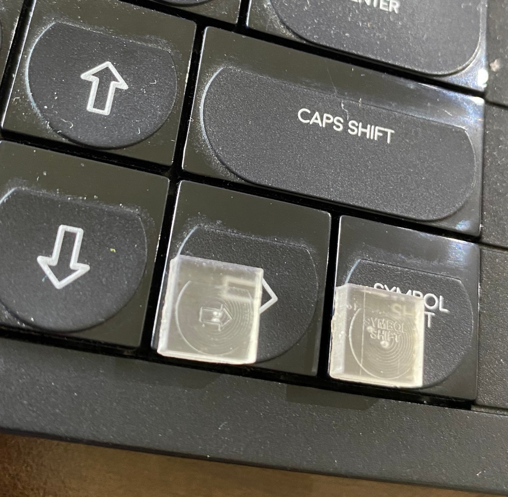
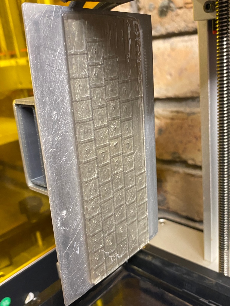
Dialling in variables, this is now the 4th attempt and each time it’s getting better 🙂 (other than the first time which some keys looked great on the other printer!)
Have done a good amount this past week – Finally received the 2mm pitch ribbon cables so decided to test the boards……
…Aaand, something wasn’t correct – lots of keys jumbled up.
So, had to spend an hour or two diagnosing!…and to do that I knocked up a quick spreadsheet to cross reference. I had a similar problem with my C64 Mini, so suspected it was simple ‘swapped pins’ – But was worried as to how I goofed it up….
Should be here next week, not long till I find out how badly I’ve cocked them all up and how much work needed for a re-spin for production!
I purchased 2000 switches so can re-spin and re-test one, possibly two depending on which one (the Amiga needs 500 switches for 5 keyboards, spectrum needs far fewer!!)
Exciting times, now gotta get off my bum and fire the resin printers up.
Yep, these are WORKING keyboards for the
The A500 Mini Amiga
The C64 Mini Commodore 64
And
The Spectrum Next Mini (an Xberry Pi case) which is a 50% X &Y (100% Z) scale next mini styled case.
The Keyboards (Spectrum Next Mini, The A500 Mini and TheC64 Mini) are actually being made right now at JLCPCB – The Keyswitches arrived, were checked and manufacturing is go!
So, in the meanwhile, I’ve been playing around with the Next mini case – My original design was a proper , almost exact 50% scale. That means you place 4 of them in a square next to each other 2×2. Then Stack another 4 on top.
So That’s EIGHT spectrum Next mini’s, stacked in a ‘cube’ of 2x2x2…
Recently, Some clever guy Released the Xberry Pi, A ‘credit card’ sized Spectrum Next that can fit in a Raspberry Pi case…
Of course, it wouldn’t fit inside my Next Mini! There’s just not enough space inside to fit a keyboard and this….Infact, this thing needs exactly the same amount of height as a full sized Spectrum Next!
So, after some re-jigging, I’ve now made the Next Chibi (name, work in progress)
This version keeps the impractical 50% scale keyboard…BUT
It’s a 100% height Next!
(So you can only fit four in the space of a full sized next)
the 2000 custom switches are being sent to @jlcpcb, To use them all up, I’ve ordered 15 of the next mini keyboards to prototype
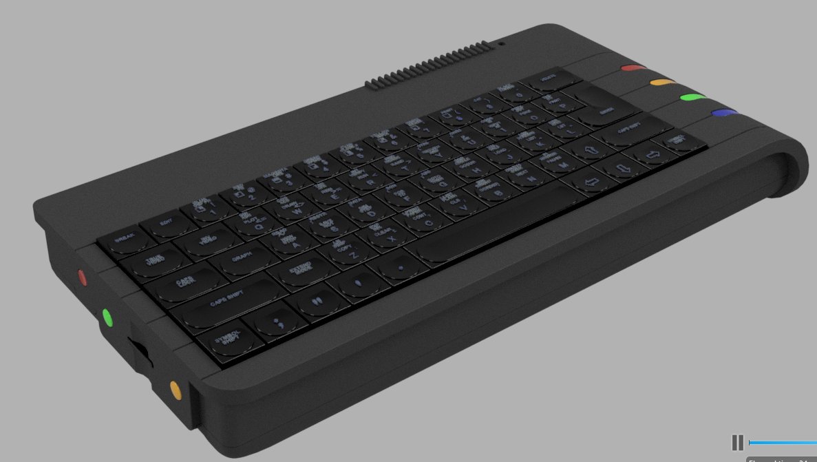
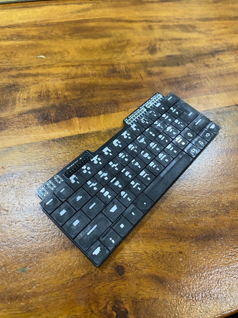
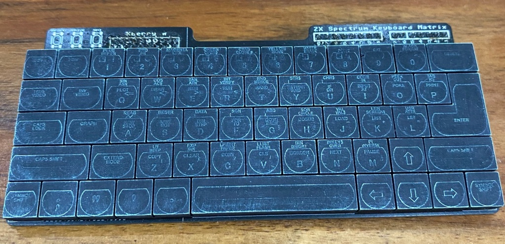
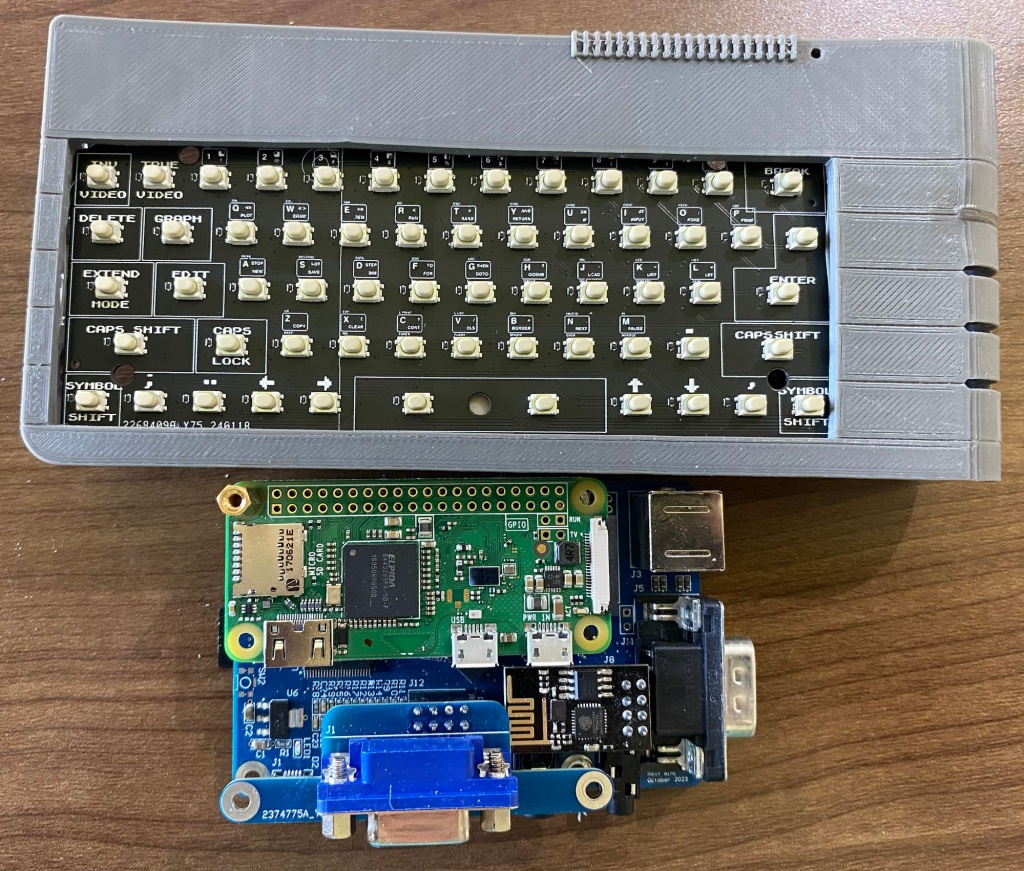
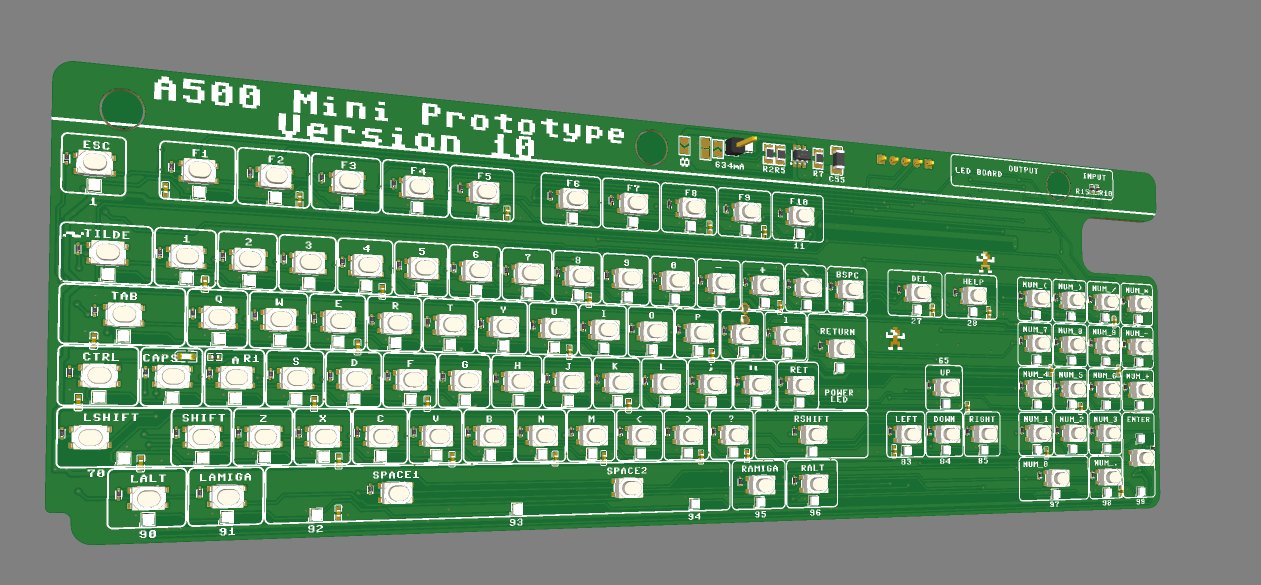
Front of the First prototype
Rear of the prototype
The rear of the Spectrum Next Mini keyboard has a Raspberry Pi Pico option – I’ll create a PRK keymap – this will allow people to use the device with USB ‘things’ like raspberry pi’s, PC’s or even the A500 Mini 😉
Without the Pico, it’ll work as a standard 5+8+2 next keyboard, or, for it’s main intended use – with the Xberry Pi’s 10×2 header.
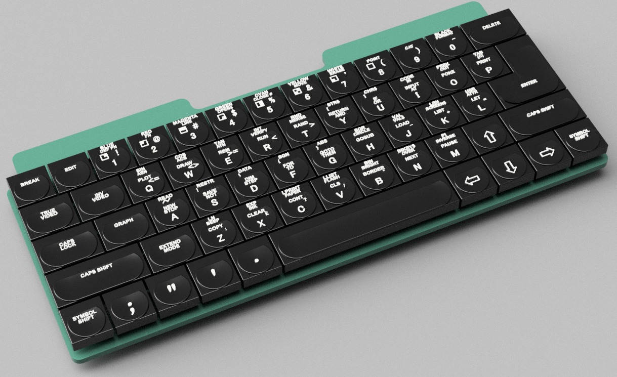
Render of the prototype Spectrum Next Mini keyboard.
I’ve also ordered 10 of the A500 Mini Prototype – this one’s on version 10. it should be the final one before I can hit ‘production’ – everything fits, no reason why it won’t work. This revision just adds a little circuitry – which is easily bypassed if it doesn’t work
These are the first brand new work that i’ve done on the inserts. The previous LED inserts were hacked out of the STL’s the ZX Spectrum Next team released some time ago. Since those early mesh hacks, i’ve learned quite a bit more on Fusion360 (which is entirely free for makers!)
Not much of an update, but i’m slowly picking back up on this again, personally, it’s been quite a tough 2021 , leaving me with little capacity to do fundemental development stuff…On the plus side, i’ve been in ‘something shiny’ mode for quite a while and literally shotgun blasting ‘fun’ ideas for new things, a few of which have been developed further and you’ll read about once they’re better baked.
Have been having a little bit of a creative Block with the Blinkenator. It’s a typical story where ‘something shiny’ has been spotted and has been taking up the small chunks of time I’d normally allocate to this stuff.
I’m awaiting on those Pogo pins to test the next revision…….But, have also seriously re-thought the programminator / tester device…….And, we have what you see above
ROUGH IDEA OF CONNECTIVITY, The programminator sits ‘underneath’ the J15
The Plan.
40 Pin Raspberry Pi connector will allow some ‘playing’ around with the ESP device, and programming of the Arduino. I’ll need to figure out exactly how to write the software to do it- but, there’s dozens of tutorials out there so i’m confident.
Programming could also be done via a standard 6 or 10 pin ICSP device (that can be bought for a few quid off Ebay) directly on the blinkenator itself, or via the 9 pin connector at the bottom – which breaks out to the Programminator.
The Programminator also utilises the J15 connector of the Blinkenator – This should be a great way of testing the new Pogo pins connections as my Specnext J15 is fairly well shot
There’s 2 new holes – 57mm spaced (same as a Raspberry Pi!) which can sit standoffs which match the positioning on the programminator (rasperry pi footprint)
Took quite a while to get this far – now at least you should be able to see the LED’s doing their stuff whilst connected to a Pi and a test board!
June 2021 Revision of the Blinkenator
I’m very close now to getting this new board done as a BETA….next step is to print out, test fit and tweak
In other Interesting news, JLCPCB ‘s NEW version of EasyEDA exports OBJ files! I’ve literally just discovered that you can EXPORT a 3D model of your PCB.
That’s a game changer!
A quick Bodge-up with Microsoft 3D Builder
Why it’s a Game Changer – Simply use Microsoft 3D builder or Tinkercad (or anything really, those two are just superbly easy to use
Assemble your bits – whack ‘print’ and, send to a 3D printer. Or put into your favourite slicer program and do the same – I’ll have a little bit more of a play tomorrow – it’s 11PM now. Now, to use the Resin printer or the Filament one 🙂
Oh, as for the ‘something shiny’ that’s come along…..Checking the logs in Fusion360, I started back on the 8th February. Since then I’ve easily spent 200+ hours editing, tweaking, Learning. I made the first 3D print last week. There will be many more prints till it’s ‘final’ .
There’ll be a few versions of electronics inside, Basic version will likley be some type of Raspberry Pi – Compute Module , A design is well underway. I’m also possibly thinking of dabbling in FPGA, though a 6 layer double sided PCB is a bit daunting, I’m designing one anyway after gaining a big bit of help from someone who’s already familiar with FPGA’s
I’m being vague as I really don’t know where this one’s going. I’ll need to show this publicly, once it’s done and then see what occurs. I’ll need a new, larger resin printer for sure if it takes off though, it uses the entire build volume of my Anycubic Photon Mono printing off the two larger pieces at an angle!
I’m still trying to make this darn thing solderless….and, I have possibly a lead, which ain’t cheap…but will allow me to offer two versions.
Those gold things are pogo pins. But, slightly less common ones with a 1.2mm diameter pin part. This should sit quite nicely into the Next’s 1mm holes in J15…..except in my excitement, I forgot about that darn keyboard connector!
Using these requires yet another redesign, but a relatively minor one that only needs the connector stuff soldered on the reverse of the PCB…
On the plus side, this could make end user fitting of the inserts a little easier 🙂
As for ‘expensive’ – those pogo pins are around £1 each and at least 6 will be needed, more if the wifi relocation is used!
Just a quick photo of me holding my Next up against a snowy scene!
And aaaaanother Beta!. Doing significantly more testing this time round
Still not quite over the roadblock for the solderless BETA, but have kinda proven that the ‘programminator’ idea doesn’t really work as well as hoped. BUT, i have proven that a simple 9 pin JST-PH connector – 1.27mm pitch will work – also known as a molex picoblade style.
Going forward, this will be the way someone programs up the Blinkenator. I’ll have another board – possibly included with every blinkenator to convert this to a standard USBASP style header, unsure yet, depends on just how easy I can make the 6 pin header up on the top right to access. would be nice if people can program it up with their case closed….we’ll see
I’m hoping to double down on the blinkenator over the coming weeks, still quite a bit to finalise with the code and the LED inserts!….fun fun.
and, yes, my small digression with the 90’s miniatures is actually a disguised learning excercise. My LED inserts have some fantastically small detail. i’m now learning how to use supports properly….which will dramatically speed up development time on 3D printed inserts. and, also provide a proper path / workflow to being able to get them injection moulded….IF the budget and interest allows. My early experiments however suggest, I may just about be able to achieve an injection moulding style ‘gloss’ finish with 3D printing….keep tuned in!
Beta 11 had a minor cock-up in that i’d missed off the 3v3 line. I’ve also taken the oportunity to shift things around a bit, re-align stuff and generally do a lot of really picky small stuff that generally makes me feel a bit better. Except that upside down C22 that i’ve just spotted, D’oh!
Also, I now introduce 2 more members of the Super LED Blinkenator 2000 family
The Clampinator
This one, you’ve kind of met before. It’s a small ‘clamp’ PCB, but it now splits into two parts. One ‘spacer / shim’ sits in-between the Clampy larger bit, the other, is the clampy larger bit.
When installed, it’ll look a little something like this…..
Blue is the Next PCB. Red is the tiny thin break-off ‘spacer’. Black is the Blinkenator.
The Red ‘shim’ part stops the yellow clamping PCB from getting too close to the Blinkenator when the screws and nuts are tightened.
That combination of PCB’s, copper balls, nuts & bolts provides a robust electrical contact to J15 – Without needing to solder. Yes, it’s a little fiddly – I’ll make some instructions.
Another Member – The Programminator
Glorified serial to USB convertor
Now i’ve switched over to a SMT atmega chip, it needs programming. I’ve bought some of the important signals out to a PCI EXpress connector to make for me, at Bleugh.Biz headquarters to quickly program the on-board arduino and test some basic features.
I thinkn REV 2 of this board could be useful for general tinkering also, so i’ll probably do a limited run to sell if people really want them. I’ll send out a handful of REV1 of this board to the BETA testers, IF BETA12 works.
And, finally – a quick overview of the new layout and routing. I’m now confident enough in the design to use a copper pour for a much more professional finish!
Have had quite a few ‘spare’ hours to tinker these past few weeks. Finally have gotten over a little bit of a hill and put some development time back into the SUPER LED BLINKENATOR 2000
Thanks to some fellow hardware developers for keeping me sane!.
My previous choice of Micro was mainly driven by attempting economies of scale and using the same one for the C64 Mini keyboard kit as this. Also, a desire to allow people to ‘program up’ their own Blinkenator board – The Atmega32u4 is a bit of an overkill for a handful of LED’s though. Importantly also, prices of arduinos have risen quite a bit since Brexit . Changing to a chip saves easily 60% in hardware costs over the soldered on Arduino, it also saves a handful of minutes in soldering!
It does introduce a little more complexity – I now need to figure out how to ICSP – In Circuit Serial Programmin works as i’ll need to burn an Arduino bootloader to each one.
I’ll also need to develop (or modify) a Programmer to allow a more day-day use of the device over UART to USB
Next step, port the Blinkenator to the 328p, test, if it works, Order Beta11
Oh, the Ball clamps are working superbly, just gotta be careful of feature creep on that clampinator board now!
oh, probably will look at swapping the JST connector footprints to SMT – would be nice if I can have just the
Had to admit, the failure of the Beta 9 got to me a little bit. Took me a couple of days to take stock, stand back and think.
After much thinking, about life, being married, kids and generally having to work hard at a day job, remembering about that one time where that bloke ripped you off, Postulating how things can build up and get to you to the point where you just think that getting screwed and having your balls in a vice would be more preferable………..
You can come to yet another epiphany!….Screw it and put the Balls, in a vice.
I present to you……..The precursor to the release candidate for the production version….Err
Been a busy few weeks here at Bleugh.Biz industries, working ridiculous hours at my day job, keeping kids from murdering each other during the evenings……But, i’ve been getting some good tinkering time in.
Some very good progress has been made! – and this is the board that’ll hopefully, finally, once and forever physically fit perfectly
Some Notable changes
Balls! – A revised J15 connection method that’ll provide a simple and very robust connection method
Spacings – The holes for the LED inserts have been altered a little to allow easier assembly. It’s still mildly fiddly but easy enough.
Fixtures – The J15 are has now two horizontal slices cut into it – this provides a spring mechanism for the balls. it helps to PCB distortion locally without warping all of the board from Next PCB to inserts
Holes – The whole board is now held with press fit type connection. The two screws holding the Next PCB are removed and replaced with two new ones. this holds the Blinkenator board to the next PCB and the Next PCB to the case. The two holes for the screws have been changed to 5mm!
Positions – The JST style connectors have been re-located and changed from Right angle to Vertical. Now the board’s mounted above the next board there’s plenty of space underneath. The path from the Arduino USB connector is now also free so you can tuck a cable into the board permanently
LED’s – Moar Bling! Each insert location now has a LED colour on the main board. No real purpose other than to look great and provide the end users with some assurance that the board is powered up when they do their first tests with a USB cable outside of the Next
ESP-01 – CPU_RST has been changed to a JST style connector to make ease of fitting. This whole feature is still highly experimental and may not make it into final production (if it doesn’t work, there’d be no point!)
Inserts – There’s now a 0.56mm gap between the jumpers – to fit a 0.6mm wide PCB!. makes a nice snug fit. and easy also to work with – simply trial fit once when you receive your board, that’ll loosen them up. remove and re-fit into the Next
Jumpers – Lots of experimental jumpers! GPIO to arduino, TX/RX to arduino, DB+ integration enabling / passthrough…….and some secret sauce also
THICKNESS – The board’s back to a phat 1.6mm thick. this provides significant stability to the jumpers that hold the inserts in place. Much easier to repeatedly get them soldered straight when assembling
Components – The whole board’s been rationalised for component price – and where possible using @JLCPCB’s BASIC library – that saves quite some amount in production prices as non Basic items incurr an engineering fee per component. Previously 3/4 the components were Extended, now 3/4 are Basic!
Silkscreen – Tidied up and made a bit more slick……..
I’m sure there’s a few more changes i’ve missed, but that’s the important stuff.
Where from here……….IF this last board plugs in, fits well, i’ll be sending out to the key Dev team. I can then kick back, relax a little and start again playing with the software side of things, Both Next side and Arduino side!.
I’ll eventually also need to consider switching over the whole board to SMT, or as much as possible. I’m not that daunted by this as there’s quite a number of ways this can be achieved, including just putting the 32U4 straight on-board, or considering changing the micro type entirely. After all, the main reason i’m using a 32u4 is that it’s cheap, Arduino compatible, has USB built in. All those things give a great ‘dev board’ capability that people can use to simply plug in and tweak!