Decided to try to knock up a set of alchemists scales!
These bits often get broken. Quick half hour in Fusion getting the first eyeballed set done, then another hour ‘fixing’ the model once someone gave me the correct dimensions. I’m getting someone to check out the model , comparing it to the original, i’ll then put it up on Cults or MyMiniFactory
My Son asked could he have some V-Bucks for that ridiculously addictive Fortnite – it’s totally free to play, but to be ‘cool’ you’ve gotta spend real life ££ on skins . As he’s done quite well at school, I’ve decided to reward him with some, but rather than just hand over a string of characters on some paper, I’ve spent a little more time being creative
quick couple of renders and timeline of the coin
If you fancy playing with this yourself or editing it – I’ve uploaded the Fusion360 f3d file to Google Drive – Here
It’s all eyeballed, but seems close enough to the original. It’s quite a simple item to do, the hardest part to figure out is the tapered top of the coin – which is a simple ‘side profile’ then revolve to create the coin. The rest is a circular pattern to create the curved lit up pieces, then a handful of extrudes and fillets
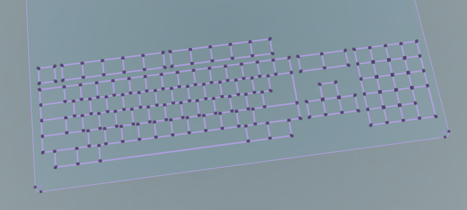
First Proper scale PCB layout for the A500 Mini. it mostly looks like it’ll work – BUT, there’s some problems.
I’ve highlighted the problematic switches with white blocks
The Problem – Having switches at 0 degrees or 90 degrees means at some point, due to the staggered keyboard, some will overlap. I’ve spent a few hours optimising the rotation of the switches to reduce the number of overlaps to a minimum, AND, to give all those overlaps a common ‘thing’ that possibly provides one way of easily fixing this.
Zoomed in view
I’ve made it so that Every ‘overlapping’ switch has the bottom left pad causing the overlap. This means, with the right switch type, I can simply cut off this leg for each of the 8 problematic switches and have the keyboard work just fine!
In Most SMT switches this size, there’s 4 legs, but often only 2 are used, (single pole) or sometimes there’s 2 separate switches inside (double pole). provided I use the correct two pins, they should just work fine with 3 legs soldered in. This isn’t exactly an industrially abused keyboard, so 3 legs is plenty of mechanical support.
BUT – I’m unsure if I could ever convince a PCB assembly house to cut a leg off the switches and solder them at a reasonable price, meaning that I may need to solder these 8 manually myself.
There’s a potential other fix also – Rotating the switches at ‘odd’ angles!
If you squint closely, there’s now no overlapping pads on the switches, However, this comes with potential issues
1 – Manufacturing, companies may not want, or be able to put switches on the PCB at arbitary angles like this
2 -Available space within the A500 Mini is currently unknown, which may not give me enough height to be able to do this.
Physically, a 6mm switch, placed at 45 degrees ‘just’ fits within the available 9mm envelope for each 50% scale switch
Rotate that square and you get a circle – which is less than 9mm, which is less than the keycap size!
What this means –
If I rotate the switch, I will not be able to have a recess on the keycaps. On the C64Mini, to keep the keyboard profile height correct, the switches sit about 1.5mm into the keycaps when pressed down. Without this recess, the new keys may need to sit higher than they should. But, this depends on how much space is available underneath the fake keyboard in the mini – it should be possible to add some spacers in to bring the height back down.
The switches sit inside the keycap on the C64Mini keyboard kit
So, The big summary is, Right now, there’s no roadblocks to making this work. a Fully automated production is preferable to bring costs down, so i’ll keep working down that route.
Things to do –
Contact PCB manufacturers to figure out manufacturability
Early days – Square keycaps to create a layout grid in EasyEDA
A little more advanced
Little bit of progress now – Thanks to this superb thread – and some other random pictures, I’ve gotten fairly close dimensions to a proper Amiga500. Same old story, Mine’s down my parent’s in Wales and I procrastinate over picking it up , so waste too much time analysing, measuring stuff online! It’s not accurate, but is close enough to get a 50% scale PCB layout done now, and tweak accordingly once the real A500 Mini is released
Incidentally, someone confirmed that square keys are 18mm on a base (thanks Dan) from that single dimension, i’ve been able to recreate most of the keyboard, with only now some uncertainties as to the remaining key sizes.
Why I’ve created this CAD – to use as a template to create a PCB!
Project the ‘keyboard’ bodies into a fresh sketch
It makes creating a ‘clean’ Sketch really easy. Just project the switch bases onto a fresh sketch, Export that sketch as a DXF….then import DXF into EasyEDA..
Voila, a 100% sized Amiga keyboard outline imported into EasyEDA
Of course, I’ll need to scale this lot down 50% to ensure things’ll fit in the Mini!
In some good news, I may not need to fully design the CAD for the Amiga Keycaps as someone in the scene has reached out and offered their CAD designs. Best case, I can simply modify their designs. Worst case, I can use their designs to measure the curves and ‘simply’ recreate in Fusion360. Either way, it means it’ll be a LOT quicker than the C64 Mini’s keycap development
Finally, onto the PCB design – I’ve already replaced the horrendous keyboard matrix schematic with one more resembling the genuine Amiga’s. Unlike the C64 Mini one, this one won’t be fully compatible with an actual Amiga due to there being some periphery circuitry to convert the matrix into a serial format for the motherboard to receive. BUT, keeping the same matrix – for everything other than the ‘standalone’ modifier keys should help some people to do ‘other stuff’ with this.
Oh, and I noticed that some of my previous assumptions about the 32u4 being used in the Mini were incorrect – It’s a bit bigger than I’d realised. it has 26 GPIO (kind of) when used in the raw chip form!…I thought it was 20 (D’oh!) that means you can (in theory) have a matrix with 144 switches AND a couple of pins left over for LED’s!!