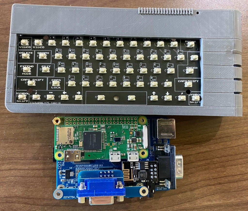
After a few hours of fault finding, PCB bodging and praying for leniency from the magic-smoke letting out gods….
I’ve plugged the keyboard in to a somewhat nekkid A500 Mini.
Now I’m torn between carrying on working or owning all the high scores!
Heck, I could procrastinate heavily by firing up workbench and give the keyboard and mouse a really good seeing to!
But…I won’t!
The hardware is now fine, I’ve adjusted the schematic to fix the issues.
I’ve also done a little DFM and used larger, cheaper anti ghosting diodes due to finding issues with two of the teeeeny SOD-923 diodes preventing the CTRL and Left Amiga keys working.
(You can just about fit 5 smaller ones in the whole footprint)
These larger diodes should minimise Pick and Place issues at the PCBA company as they’re easier to grab and likley will have an easier soldering temperature profile when next to the relatively giant switches.
Larger diodes will also provide more test points , which makes testing easier and quicker!
When making large batches, every minute saved adds up quickly!
If I make 100…and testing time is reduced by 2 minutes due to adding diodes, that’ll be over 3 hours saves just on one test!
You can see how a weekend would quickly get eaten up and achieving very little!
Should be here next week, not long till I find out how badly I’ve cocked them all up and how much work needed for a re-spin for production!
I purchased 2000 switches so can re-spin and re-test one, possibly two depending on which one (the Amiga needs 500 switches for 5 keyboards, spectrum needs far fewer!!)
Exciting times, now gotta get off my bum and fire the resin printers up.
Yep, these are WORKING keyboards for the
The A500 Mini Amiga
The C64 Mini Commodore 64
And
The Spectrum Next Mini (an Xberry Pi case) which is a 50% X &Y (100% Z) scale next mini styled case.
Tad hungover on new years day, plenty of time to ruminate, so…decided to work on the last (which is the first!) of the keyboards…had a solid 4 or 5 hours to myself today so made a lot of progress!
Have finally made the C64Mini one in surface mount – Now i’ve sourced a supplier of suitable, well priced keyswitches, I’ve felt it worthwhile to re-visit this project…
What SMT means – Very little soldering needed for this prodcut. Just the Arduino pro-micro at this time.
I’m hoping this makes the kit much more accessible, many will put their hands up and state that the 600+ solder joins needed on the old one was ‘painful’….
Some pics!
Top of the board – based on the modified 4.1
Bottom of the board..
Next step is changing the schematic over to use the much more readily available Raspberry Pi Pico or even creating a dual footprint board so you select which microprocessor to use, either the 32u4/Arduino Pro Micro or the Raspberry Pi Pico.
Unsure how i’ll offer the kits, I may well just pre-solder the microprocessor on so it’s a truly plug and play kit!
Still have to route the board, which will take a couple of days.
Also have started re-designing the keycaps from scratch – the old CAD is nigh on impossible to manipulate due to being so complex (was my first complex CAD project after all), so it’s easier to start over – and…I’ve gotten this far after just a week or so of playing
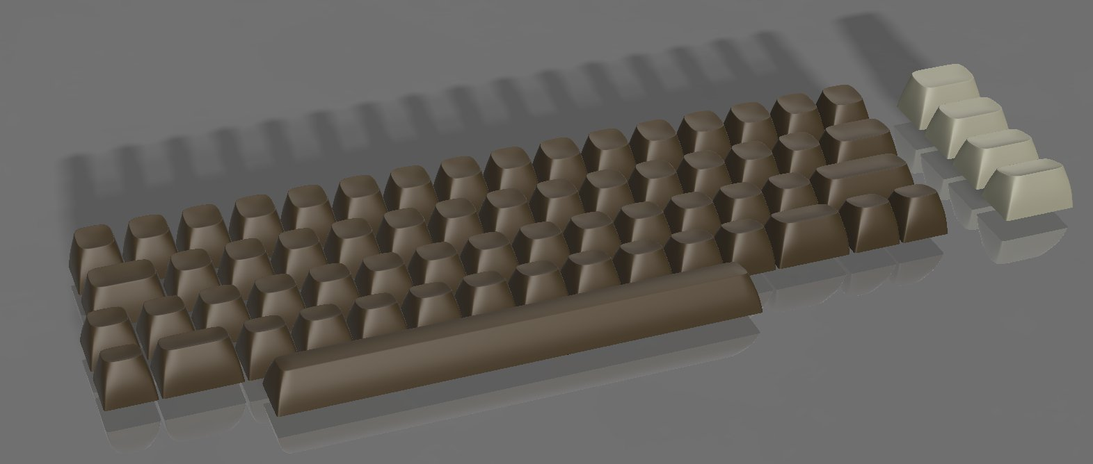
Keycaps re-done – Just needs the lettering and symbols!
I’m hoping to get this finished in time to add to my batch order of Next Mini and Amiga mini prototypes
*any colour available as long as it’s beigey brown
Have spent the last week tweaking, adjusting…probably too much really. Likely i’m actually procrastinating about making this thing physical. The new stems and locking mechanisms are are all aligned and merged in with the keycaps!
There really ain’t too much left now on the keycaps. Some minor adjustments will be needed to the stem – It’s parametric – so I print, fit, adjust one parameter which changes all keycaps at the same time (unless something breaks) and re-print.
Have made final tweaks also to the main PCB – I’m on version 11 of revision 9 now!…Again, too many little tweaks here and there, I really must fire the printers up!
I’ve been tweaking away, adjusting the EDA (the PCB via EASYEDA) and the CAD (the keycaps via Fusion360)…There’s nearly 100 bits that need to line up for it to all go well.
Previously, with my C64mini kits design, i’ve broken out the vernier calipers , measured, tweaked, printed, measured, tweaked, printed…….until everything fits just right!
For the A500 Mini Amiga, the ‘about 43%’ scale means the keycaps are just too tiny to shove underneath my ‘go to’ 5.8mm x 5.8mm switches . In addition, soldering 60 odd switches, another 60 odd diodes, and the arduino is a tad arduous, so change was needed. I’ve jumped to Surface mount style components
One advantage of Surface mount – Machine assembly – I’ll be buying in the boards mostly populated!.
The machines that assemble the boards use a file called a ‘pick and place’ file. Essentially a CSV file with co-ordinates!.
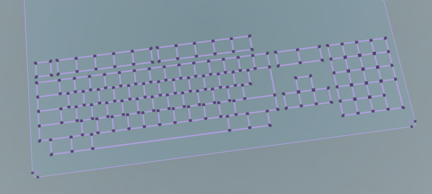
I had a ‘play’ with that CSV file, imported it into excel and plotted the co-ordinates
That looks suspiciously like a keyboard!
Imported them into Fusion as a Spline – The control points are the exact centre of where the keycaps are!
I just needed to align a point with one i’d already ensured was perfect in the CAD….and
The ESC key is perfectly located….
The centre of the stem of every key is perfectly aligned with every spline control point….Which comes directly off the Pick and place data of the PCB!
By overlaying the co-ordinates used to place the switches on the CAD model, I can now be very assured that the stems are located within the keycaps correctly, which are located within the keyboard…
or, in otherwords, it should all align, and hardly any 3D printing fake PCBS / jigs, samples, reworks needed…
I keep working with EASYEDA from JLCPCB as it’s just ‘easy’ and their PCB part has a great Export 3D model. For us metric types, just scale it by 0.254 and it fits like a glove. Very useful to align electronics and plastics in more complex models.
The new switches arrived
W0oOoot! Hear Teh Clickz… Clickey clacky. The custom made sample switches for The A500 miniature Commodore Amiga working keyboard project have arrived. They look great, sound great! And best of all, if they work great, I can improve my c64mini kits! pic.twitter.com/T51d1LwiLF
So, now to tweak the CAD to match the switches, make sure my resin printers are running, hand solder up a bunch of the sample switches onto an early revision keyboard, test and…
The original software that came with it was ‘crap’ and I struggled to get any scans out of the thing. But, an hour ago, I downloaded the latest version (from here )
and, ten minutes later, after two geometry and 1 texture scan merged, I got the below! – woo
Woo! first scan
Having an accurate scan helps a LOT when recreating things in CAD. Yes, the switches don’t look great, BUT, they’re 7mm squares – what I’m seeing, for the price I paid is, frankly amazing, AND, there’s quite a lot of improvement to be had.
So, next steps – Scanning larger things, and instead of working from photos as a canvas, I can use the original 3D item to create the angles! it’s going to be an interesting few months
That was quick! – It’s amazing what’ll come to you at random moments.
I was looking at some uneven fitting panels on a car earlier today and wondered, ‘why can’t the gaps be smaller?’ –
Well, my first idea is to simply see what happens when the gaps between the keycaps are smaller……..
If there’s no room for keycaps to wiggle, they won’t wiggle! – that’s the theory anyway – Prototype is on the printer as I type.
If this ‘rough and ready’ bodge works, I can knock out a more elegant solution that’ll look much better :-), it’ll involve going right back to the beginning, but…ho-hum, such is the nature of product development!
The idea is currently on the printer! – this is a ‘zero cost’ solution that may reduce keycap wonkyness to a level that’s acceptable.
The next idea introduces double the 3D printed parts and some extra parts on top of that – BUT, it’s still a very cheap solution compared to the alternative…..
Have been steamrollering ahead with the keyboard, and making rather good progress – Except for this little annoyance……..
It’s annoying enough to me , and a couple of trusted others to put a freeze on this method of doing things – and to invest more time doing something else!
The problems i’m facing….
The keys rotate around a bit – which, frankly, to me, is unnaceptable.
The GOOD news –
I have a way to IMMEDIATLEY fix it, Different, more expensive switches- BUT…it will increase my COST by 400% – meaning this product needs to sell for around the £70-80 mark, which I feel is waaay too high.
I do believe I have a few other good ideas which won’t cost so much, but need quite a bit of development. I’ve gotten the keys to print superbly and quickly on the printer, so I can work to good, tight tolerances. I can iterate quickly!
SO, it’ll take a couple of months longer than intended, no worries, worst case, i’ll do a limited run of expensive boards…and a wider run of boards with keys that rotate if there’s a demand (I really hope not)
This one’s been nagging away in the back of my head for some time now…I Always wanted one of these containing a hard drive when I briefly owned an Amiga. This is a GVP HD+ / HD8. and maybe a few other products also. This design really struck a chord with me when it continued the Amiga 500’s contours rather than just shove a box on the end.
No idea what I’m gonna use this for – likley a USB hub or ‘something’
This’ll need to be printed to ensure everything aligns, some of the proportions don’t look right – but seem to measure OK.
Have already updated the rear ‘fins’ they were just too long in this shotFirst time the shell command has worked well for me!
So, whilst waiting, I’ve been playing around a little with the CAD and the ‘extras’ for the keyboard kits – the Real Mini 42″ scale floppy disc.
The cocnept is – to have a ‘working’ floppy disc that you can play games off.
The concept, once again!The Sliced and supported Floppies!!Real mini floppyReal mni floppy rear
Still some work to do optimising, but i’m rather happy with this second attempt at printing. The metal part has been cut out on my KNK ZING vinyl cutter and has been extracted from a projected sketch.
That works for the Amiga side – But, people will need a way of getting the games onto the floppies , so – Early days yet, An External mini floppy disc drive for a PC!
Cutaway view
A 1011 Clone!
This was surprisingly quick to knock up . I found an image of an eBay sale, imported as a canvas, ‘traced the canvas’ and set the scale around the floppy disc slot. I’ve never owned one of these so had to work from many pictures. Still a lot more to do, but fundementally, i’m keeping the exact same PCB’s and mechanism / holder that i’m creating for the A500 Mini. Just putting it in a shell and using a different USB cable….
I will be releasing the design files publicly for this thing so anyone can print up / adjust and make their own ones as international postage gets expensive for things larger than 25mm high here in the UK…I’ll also offer up these for sale with keyboard kits
And, if you’re wondering, just how many picures…and files needed to create a floppy drive and disc…….Here’s a quick snapshot of my A500Mini folder – just for the floppy! and these are the ones i’ve kept for now….
I had somewhat of a PETSCII induced fever over the past few weeks, one that needed Sating before I could practically start anything anew, or even continue anything existing……..
So, when I (eventually) re-make the C64Mini keyboard kit to be less soldery, more easierer and betterer, It may well have PETSCII on those keycaps, for all your milliputty smudgery into-ey goodness!
A500 Mini Prototype 2 is in the post, Every C64Mini keyboard kit and parts have been posted – I’m finally fully up to date!
Three PCB’s are pretty mich ready to go . Just last minute checking, double checking, triple checking needed!.
I’m lacking lemmings on most of the boards, but be assured, there’ll be a few on the production units.
I’ve also now pretty much finished the keyboard CAD…Had to do yet another iteration to allow for the new switching mechanism i’m using..It’s really been a case of design, print, test, iterate, repeat!…Still ‘a few months away’ as always, Real life is taking over a little, meaning less time to perfect this lot.
On the plus side, I really do think this Prototype 2 will be ‘good enough’ for general testing and useage. Everything after prototype 2 will be geared to making it easier to install and add (or remove) extra features. Lots of pics after the break……………..
Made loads of ‘progress’ on the A500 Mini keyboard!
Yesterday evening was mainly procrastinating and playing around with Printed Circuit Board silkscreen / soldermask / copper to optimise the speed at which in could display many sprites simultaneously.
Quite a lot of progress, but it doesn’t look like a lot of progress.
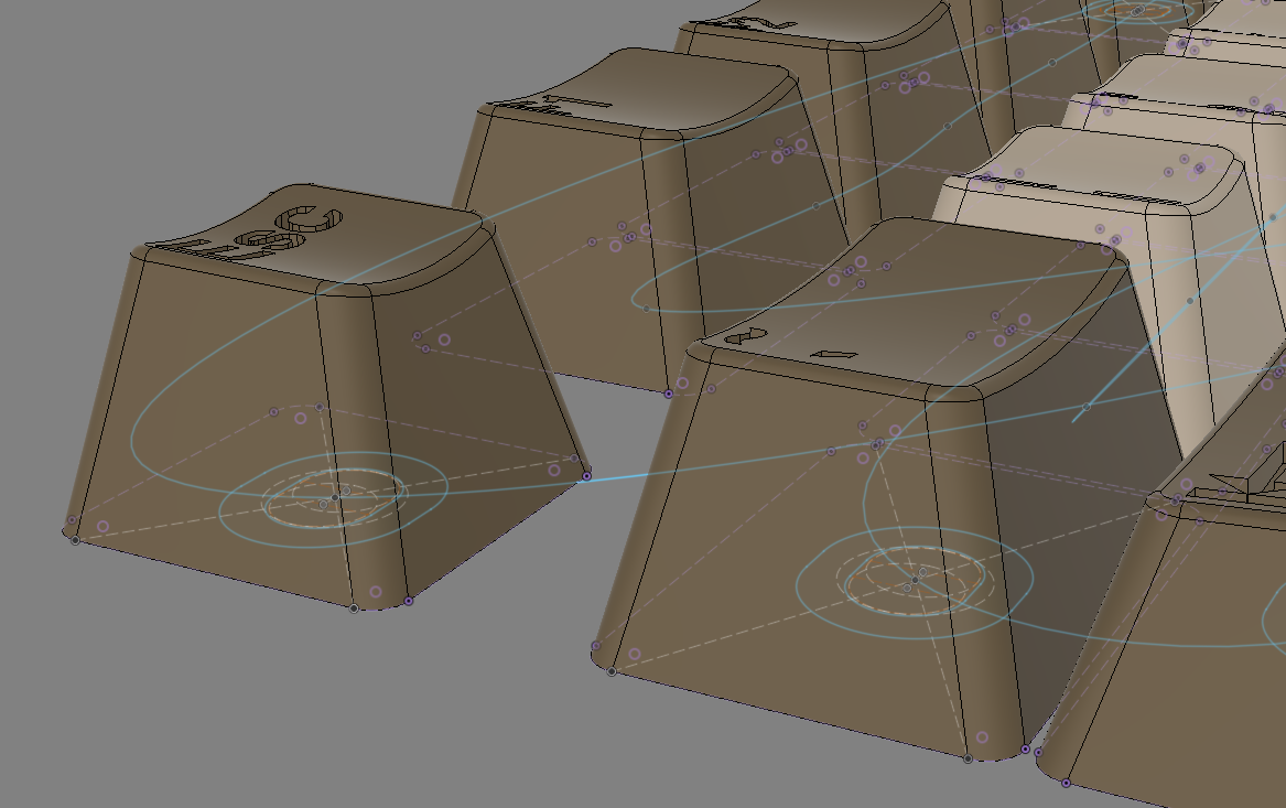
Firstly, I’ve had to re-do most of the keyboard CAD – I simply didn’t like the ‘blocky’ effect of the wider topped keycaps I’d created – as you can see below they look a lot more square in real life than they did in CAD…
I’ve now clocked well over 200 hours developing this set of keycaps, likley there’s going to be tens more tweaking / optimising!
So, along with the less blocky (more slopey) keys, I’d discovered my workflow in CAD had created tapered keys – the tops when viewed from above look like parallelograms, wheras the original Amiga had more square keys – it was quite a lot of work to alter this – see the parts below by the red arrows – the bottom bit is in towards the middle more than the top bit.
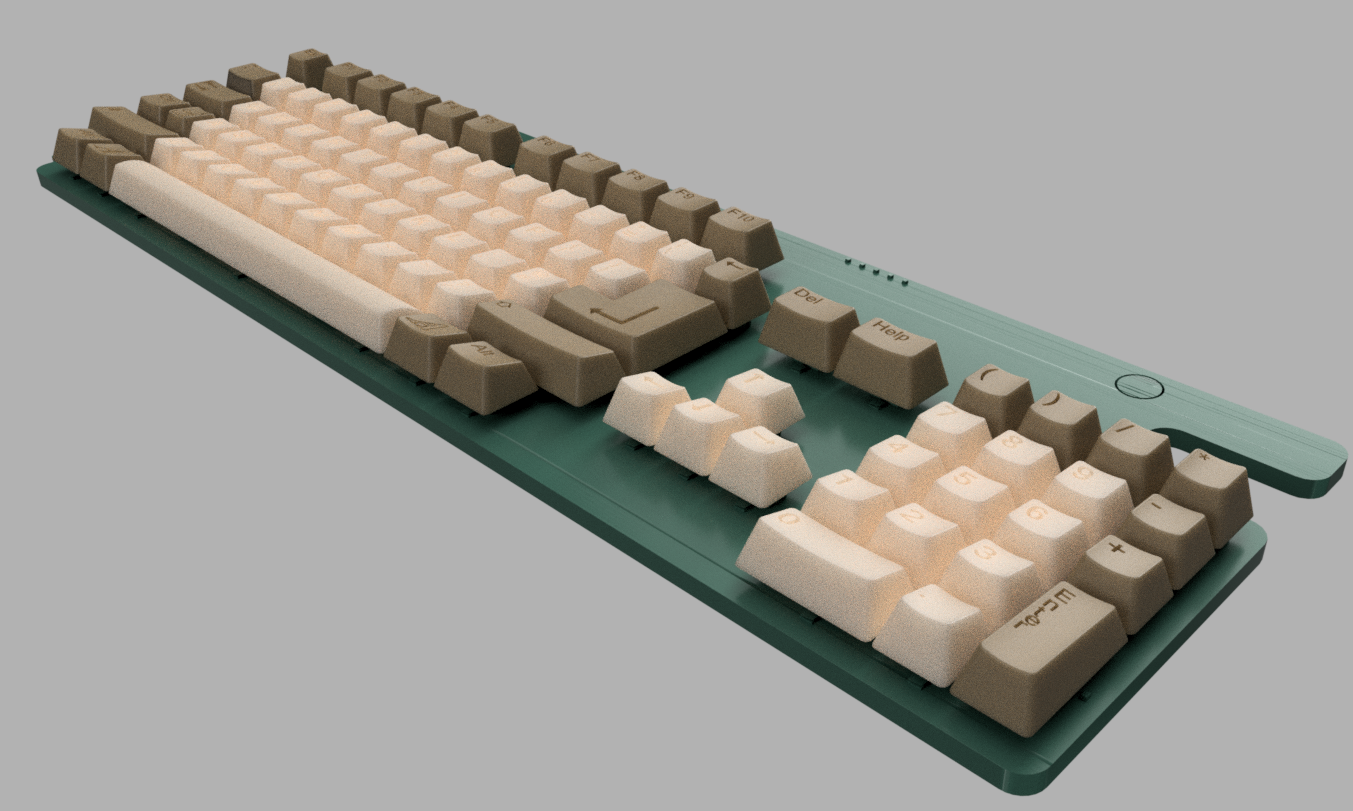
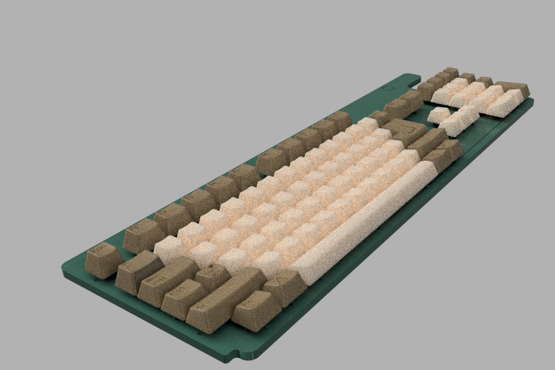
Have been tweaking things over and over, I’m now finally ready to…….
3D Print a sample!And, the complete thing
I think there’s going to be a few people out there actually using this keyboard in anger, so i’ve widened the keyswitch tops a little and added larger fonts to make it easier for someone to fill in some colour if they chose to do so.
Some other progress –
The Floppy Disc insert! – a FULL scale floppy disc fits well
I’ve refined the floppy disc insert thingy – I really think I can make this work – lots of parts on order so i’ll iterate this design over the coming weeks. I’ll do the first prints of the plug in module soon
Alternate View – with the Clamp PCB in black, the A500Mini PCB in green
Speaking of prints….
I knocked up a few of the mini-Floppies. Printed in various orientations to see if it’s even possible to do these. The best print is the angled one..Turns out, it’s going to be tricky as can be seen from the various failures above. Have re-designed a little and will run off some more sample prints soon. The supports on this one will be critical and hopefully not so wasteful as the C64mini keycaps were.
And, almost finally –
Here’s a collection of ‘stuff’ rendered so far. The Keyboard PCB is unfortunatley upside down – due to the way I started modelling stuff, no big deal but makes the renders look odd. The case slopes don’t need to be modelled (at this time) so i’ve just left them flat for now.
There’s loads of parts waiting to arrive in the post, but there’s also loads I can be getting on with, not just on this project, but on numerous others also!
I’ve spent a couple of days designing, and and a today, spent nearly a hundred quid at JLCPCB ordering a bunch of prototypes
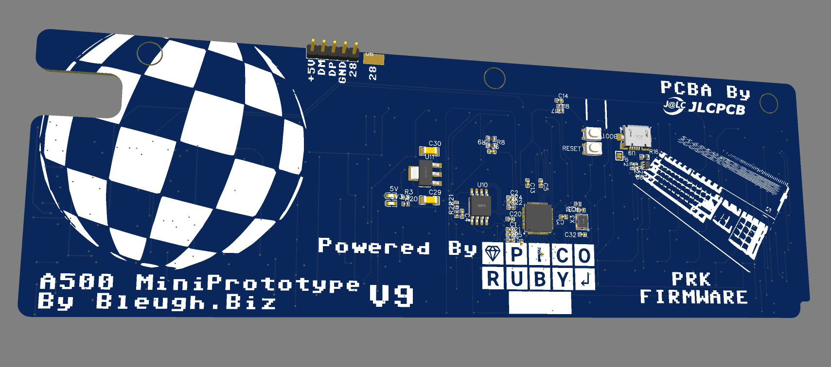
The first revision of the Keyboard PCBFirst ‘space sample’ of the top mounting board. Floppy Disc Micro SD card holder!Rear of the floppy discc.
I had to bite the bullet and spend some money as I now need to move on with the Keycap CAD. I have a big concern about the fitting of the printed keycaps onto the smaller switches. I’ve gone with ALPS switches as they used to be a huge brand name back in the day and i’m hoping should provide some consitency.
The prototypes will help also to test and develop the PRK Firmware i’m planning to use.
The ‘Clamp’ adaptor is fairly non-functional. It has a Rasperry Pi Pico footprint onboard and a 40 pin FPC style connector to act as a ‘stand-in’ for the Raspberry pi Pico which is currently on the back of the main PCB.
The whole idea of the ‘clamp board’ is to allow an ‘ease’ of installation – I’ll use some Pogo Pins to sit on the test pads by the 3 USB sockets on the back of the A500 Main board.
The plan is to have a basic matrix keyboard PCB, which connects to the clamp board via the 40 pin FPC.
The clamp then accesses the USB and hopefully it can all be fairly easy to assemble.
I’m also testing the Fake floppy connection with the clamp board – no idea if that’ll work or not, we’ll see.
Now the long-ish wait for Aliexpress to deliver my connectors, pogo pins, and a couple of weeks for the Cheapest post option of JLCPCB to ship the assembled keyboard! – nearly 100 switches and diodes on this one, those can be automated in assembly. I’ll need to hand solder on the rear the FPC connector but those are easy enough!
Progress to date has been surprisingly quick – most of the ‘easy’ stuff is now done and I’ve added some extra functionality. Most of the research is now done – have spent waaaaay too long googling connectors, Pogo pins and component types / dimensions.
First print of the keyboard PCB and CAD fitout – pretty close
My workflow generally is to eyeball, sketch, measure, adjust….Then when it’s close enough, i’ll print on paper, adjust in CAD, print again then………3D print
a 3D printed space sample
I’m quite chuffed – the first 3D print seems to fit reasonably well! – there’s some adjustments needed, mainly the top of the keycaps are a little too wide, but overall for a first run, not bad.
The PCB outline
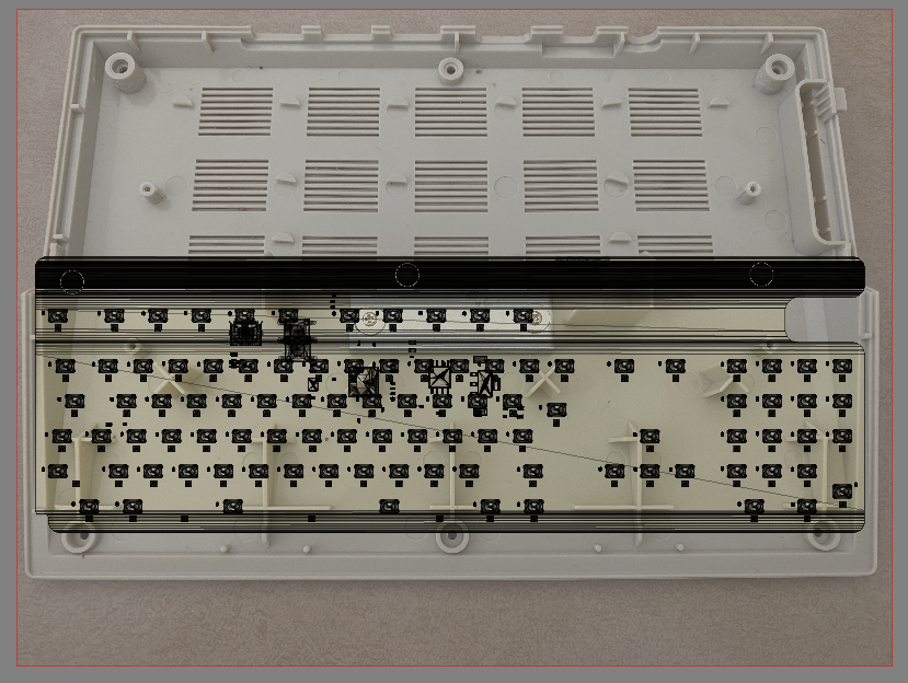
To work out a PCB outline, I’ve scanned the A500 Mini on a flatbed scanner and trace around the important parts, measuring many with calipers
the Keycap CADAnother view – the big circles are the curves / slight indents in the top of the kecaysThe CAD compared to a scan of the actual A500 Mini
Before I 3D printed the sample, I put the A500Mini on a flatbed scanner to match up the holes – as you can see, it’s pretty darn close! – you’re seeing a canvas underneath the actual CAD model of the keycaps in Fusion. The Enter key is black as i’d discovered a slight profile error, so spent half hour correcting a 0.2mm height error 😛
But, wait, there’s TWO
During the design phase, there’s a process of discovery. My main discovery for the A500Mini keyboard was that….I’d possibly need TWO PCB’s!!
If you look above at the underside of the keyboard you’ll see that there’s no space on the top for electronic components! The PCB needs to mount entirely flush to the case of the Mini. This means I’d need a PCB assembly service that can handle double sided boards (a possibility) – And to also consider a two PCB solution. There’s cost and ease of install considerations for both ways.
The A500Mini has a number of test points on the back, I think using Pogo Pins I can maybe make a clip-on PCB that can securely tap off the USB test points, meaning, a solderless install! – hence the upper white PCB that sits in place of the A500 PCB above
And, now I believe I’m going to go with a THREE PCB solution…….because…
the one with the holes in sits above the stock PCB
That’s a scale floppy disc! with a Micro SD card inquick render of the floppy slot in the case
I figured I’d go one better and make a REAL fake floppy disc. and, the best thing, after several solid days of research and CAD testing, I believe it can work 🙂 – it’ll only need two small cuts inside the A500 case and be totally stock outside. there’s a little more tweaking needed for the floppy disc design to make the MicroSD slot more elegant . I’ve ordered a whole bunch of parts to physically trial this and see if it’s viable.
So, Summary. Still a long way to go, the Keyboard itself is the priority here, the ‘floppy disc’ is just a whimsy on my part for the time being, its development is secondary and may not even make it to a real release if it’s not robust enough.
Keycap CAD – Cosmetics finished, Just needs the ‘switch’ solution figured out
Main PCB – Outline finished, needs routing, quick job to finish
I received yesterday my A500 Mini! – Haven’t even powered it up yet 😛
My assumption about the 43ish percent scale was about right – and the work i’ve done so far on the PCB pretty much stays the same – which is a relief.
However, till now i’ve been using a full sized Amiga 500 to infer dimensions. I can’t easily do that going forward as the scaling factor for the Amiga is ‘a bit weird’ – I think I can see why it’s been done, but, it’s far far easier to re-start the CAD from new…or at least shift the fusion timeline back to the beginning and see what i can recover 🙂
Much more to do, will update later as there’s also a few ‘gotcha’s i’ve found, and a few ‘woo’ moments also!
Dimensioned to within about 0.3mm Spmeone should hide my screwdrivers
Had a major ‘procrastination’ research binge over this past week, trying to figure out just how I could cheaply and reliably get 3D printed keycaps onto tiny switches.
I’ve found I think two ways that can be successful.
The first – a small tactile switch, with an ‘oval’ or keyed button. The A500mini’s keys are probably just over 7mm square, I can’t use the 6mm switches i’ve previously used as there’s not enough space.
Something like the below could do the job – it has a slightly tapered switching bit in the middle, so I can do push fit keycaps that should grip on. it’s also 5mm on a side, and 3mm on the other, this frees a huge amount of PCB space up, BUT, it’s still quite ‘large’ and the top isn’t tapered as much as i’d like. visually it looks fine, but datasheet suggests it’s straight
There’s also an older, more ‘retro’ type of approach. So, i’ve gone and knocked up a very rough CAD drawing – it’s innacurate, until I get an actual A500Mini in my hands…
and i’ve gone and emailed half a dozen companies to request some MOQ’s. and some pricing!. I’ll fill this in later with more specifics
So, that means getting firmware working should be a breeze.
There’s becoming quite a few ‘RP2040’ public circuits available now, so that part’s done and dusted on my PCB, all i’m really waiting for is to get some accurate measurements so I can knock up a prototype!
Minor update on progress…made the schematic a bit clearer for me to understand, also am doing a dual footprint style setup – where I overlay multiple component footprints incase one becomes hard to get.
I’m also creating two ways of driving the matrix, an on-board RP2040 chip and, if they become hard to get, a seperate daughterboard which can house a Pi Pico
Kinda pausing PCB development until my Amiga 500 Mini device arrives in the post, but i’ll be playing with the PRK firmware next!
Early days – Square keycaps to create a layout grid in EasyEDA
A little more advanced
Little bit of progress now – Thanks to this superb thread – and some other random pictures, I’ve gotten fairly close dimensions to a proper Amiga500. Same old story, Mine’s down my parent’s in Wales and I procrastinate over picking it up , so waste too much time analysing, measuring stuff online! It’s not accurate, but is close enough to get a 50% scale PCB layout done now, and tweak accordingly once the real A500 Mini is released
Incidentally, someone confirmed that square keys are 18mm on a base (thanks Dan) from that single dimension, i’ve been able to recreate most of the keyboard, with only now some uncertainties as to the remaining key sizes.
Why I’ve created this CAD – to use as a template to create a PCB!
Project the ‘keyboard’ bodies into a fresh sketch
It makes creating a ‘clean’ Sketch really easy. Just project the switch bases onto a fresh sketch, Export that sketch as a DXF….then import DXF into EasyEDA..
Voila, a 100% sized Amiga keyboard outline imported into EasyEDA
Of course, I’ll need to scale this lot down 50% to ensure things’ll fit in the Mini!
In some good news, I may not need to fully design the CAD for the Amiga Keycaps as someone in the scene has reached out and offered their CAD designs. Best case, I can simply modify their designs. Worst case, I can use their designs to measure the curves and ‘simply’ recreate in Fusion360. Either way, it means it’ll be a LOT quicker than the C64 Mini’s keycap development
Finally, onto the PCB design – I’ve already replaced the horrendous keyboard matrix schematic with one more resembling the genuine Amiga’s. Unlike the C64 Mini one, this one won’t be fully compatible with an actual Amiga due to there being some periphery circuitry to convert the matrix into a serial format for the motherboard to receive. BUT, keeping the same matrix – for everything other than the ‘standalone’ modifier keys should help some people to do ‘other stuff’ with this.
Oh, and I noticed that some of my previous assumptions about the 32u4 being used in the Mini were incorrect – It’s a bit bigger than I’d realised. it has 26 GPIO (kind of) when used in the raw chip form!…I thought it was 20 (D’oh!) that means you can (in theory) have a matrix with 144 switches AND a couple of pins left over for LED’s!!
Very early days yet – But, this is the first start for making the Commodore Amiga Mini working keyboard kit! About 1/2 way done on the matrix, then the peripheral components to go.
Then i’ll ditch it all and start over as the above is a bit of a mess ;-P
I’m currently working on a design assuming I can use the same again. There’s very few switches on the market with a ‘square’ style centre part that can capture keycaps. I have leads on a few others, but plan this time is to find surface mount versions and try to get a batch ‘mass produced’ – i.e. little to no soldering needed for you lot!
Early days yet, it’s been quite hard to ‘get back into the grove’ . here’s hoping I get this finished in 2022!
Lots of pictures here, But looks like the latest batch of C64 Mini hackers are quite the clever lot. Batch 21 has been arriving around the globe, and look wot some guys gone done!
First email arrived early this morning – Vinz!, You’re a genius…..My jaw dropped!
Some explaination of the pictures…….
In photo 1, I used a ruler with double sided tape to solder switches as straight as possible
in photo 2 I used white putty to color the caps
in photo 3 I cleaned the excess putty
in photos 4 and 5 I painted the caps with matt transparent water-based paint, in this way the filler is protected
Switches will be here in a day or two!, i’ll email everyone about kits shortly.
Purchased some ‘old gold’ pigment from https://www.resin8.co.uk/ and tried it with the keycaps for something different. Came out ‘ok’ – nice and gold on the top, but lacking in gold on the sides. I suspect the particles weren’t being agitated sufficiently and sank to the bottom.
I’ll try again soon with a higher concentration of pigment and see how that goes before considering offering these as a product!