Should be here next week, not long till I find out how badly I’ve cocked them all up and how much work needed for a re-spin for production!
I purchased 2000 switches so can re-spin and re-test one, possibly two depending on which one (the Amiga needs 500 switches for 5 keyboards, spectrum needs far fewer!!)
Exciting times, now gotta get off my bum and fire the resin printers up.
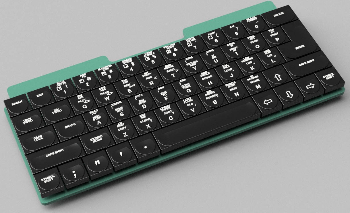
Yep, these are WORKING keyboards for the
The A500 Mini Amiga
The C64 Mini Commodore 64
And
The Spectrum Next Mini (an Xberry Pi case) which is a 50% X &Y (100% Z) scale next mini styled case.
the 2000 custom switches are being sent to @jlcpcb, To use them all up, I’ve ordered 15 of the next mini keyboards to prototype
Front of the First prototype
Rear of the prototype
The rear of the Spectrum Next Mini keyboard has a Raspberry Pi Pico option – I’ll create a PRK keymap – this will allow people to use the device with USB ‘things’ like raspberry pi’s, PC’s or even the A500 Mini 😉
Without the Pico, it’ll work as a standard 5+8+2 next keyboard, or, for it’s main intended use – with the Xberry Pi’s 10×2 header.
Render of the prototype Spectrum Next Mini keyboard.
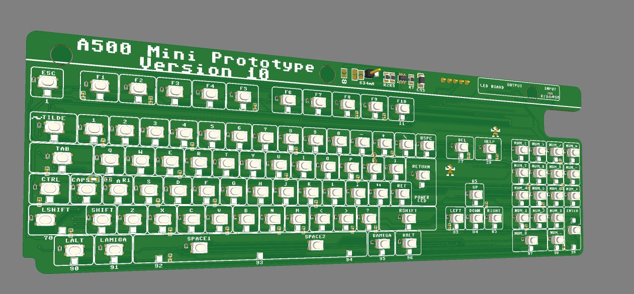
I’ve also ordered 10 of the A500 Mini Prototype – this one’s on version 10. it should be the final one before I can hit ‘production’ – everything fits, no reason why it won’t work. This revision just adds a little circuitry – which is easily bypassed if it doesn’t work
This one’s been nagging away in the back of my head for some time now…I Always wanted one of these containing a hard drive when I briefly owned an Amiga. This is a GVP HD+ / HD8. and maybe a few other products also. This design really struck a chord with me when it continued the Amiga 500’s contours rather than just shove a box on the end.
No idea what I’m gonna use this for – likley a USB hub or ‘something’
This’ll need to be printed to ensure everything aligns, some of the proportions don’t look right – but seem to measure OK.
Have already updated the rear ‘fins’ they were just too long in this shotFirst time the shell command has worked well for me!
So, whilst waiting, I’ve been playing around a little with the CAD and the ‘extras’ for the keyboard kits – the Real Mini 42″ scale floppy disc.
The cocnept is – to have a ‘working’ floppy disc that you can play games off.
The concept, once again!The Sliced and supported Floppies!!Real mini floppyReal mni floppy rear
Still some work to do optimising, but i’m rather happy with this second attempt at printing. The metal part has been cut out on my KNK ZING vinyl cutter and has been extracted from a projected sketch.
That works for the Amiga side – But, people will need a way of getting the games onto the floppies , so – Early days yet, An External mini floppy disc drive for a PC!
Cutaway view
A 1011 Clone!
This was surprisingly quick to knock up . I found an image of an eBay sale, imported as a canvas, ‘traced the canvas’ and set the scale around the floppy disc slot. I’ve never owned one of these so had to work from many pictures. Still a lot more to do, but fundementally, i’m keeping the exact same PCB’s and mechanism / holder that i’m creating for the A500 Mini. Just putting it in a shell and using a different USB cable….
I will be releasing the design files publicly for this thing so anyone can print up / adjust and make their own ones as international postage gets expensive for things larger than 25mm high here in the UK…I’ll also offer up these for sale with keyboard kits
And, if you’re wondering, just how many picures…and files needed to create a floppy drive and disc…….Here’s a quick snapshot of my A500Mini folder – just for the floppy! and these are the ones i’ve kept for now….
Three PCB’s are pretty mich ready to go . Just last minute checking, double checking, triple checking needed!.
I’m lacking lemmings on most of the boards, but be assured, there’ll be a few on the production units.
I’ve also now pretty much finished the keyboard CAD…Had to do yet another iteration to allow for the new switching mechanism i’m using..It’s really been a case of design, print, test, iterate, repeat!…Still ‘a few months away’ as always, Real life is taking over a little, meaning less time to perfect this lot.
On the plus side, I really do think this Prototype 2 will be ‘good enough’ for general testing and useage. Everything after prototype 2 will be geared to making it easier to install and add (or remove) extra features. Lots of pics after the break……………..
Made loads of ‘progress’ on the A500 Mini keyboard!
Yesterday evening was mainly procrastinating and playing around with Printed Circuit Board silkscreen / soldermask / copper to optimise the speed at which in could display many sprites simultaneously.
I’ve tonight finished routing the new PCB and switches!
A lot of work has gone into this! It’s got some ‘extras’ , it’s also an expensive board at 4 layers , 1.2mm thick and nearly 100 switches!
I’ll get to designing the other 2 or 3 (maybe even 4!) PCB’s needed for the complete setup, then place a single order for them all, so it’ll be a few weeks till I can test this beast out!
If they work, Ill make few ‘special limited edition’ early ones to send out, I’ll not spoil the surprise extra features till they’re in my hands!
Well, that’s a wrap for idea 1 – concept was ok enough, but…it’s no-where near good enough for a production run.
After half a dozen trial prints and practice fittings, I’m heading down another path.
The Many faults include
Keys fitting poorly to switches.
Keys not fitting on switches straight
Keys just not fitting onto switches at all
The attached picture sums it up really.
All is not lost however. This is something I had to trial, if it worked, it would have been cheaper and awesome.
I have a few ideas up my sleeve…My next option is right now, considerably more expensive, but has been underway for a few weeks now, I’ll reveal a bit more once the process is done.
On the plus side, the keycaps look great in Amiga Beige! – I’ll work on the darker caps another time.
The PCB layout works great, firmware works, so, really, it’s down to the thing that always was going to be an issue, the switches!
First working keyboard keycaps are off the printer! Only this bit to show as most of the print failed 😛
Well,, 3 prints failed, I’m trying to learn how to use my Photon Mono-X, so far mostly unsuccessfully, these were printed using a known good combination of Photon Mono and Commodore Brown resin 🙂 ….and still it partly failed!!
Next, I have to optimise the design for printing. I’d added some features to make them work better, but, those features don’t translate to printing very well, D’oh! (That’s called not doing Design For Manufacture!).
Resin printing can be a hard beast to tame, especially when printing 94/98 individual items (98 if I can two keyboard types!!)
This first print is literally an ‘auto supports, Jab a few extras on, hope for the best’ quick test to prove the mechanics. When the design is finished, I’ll need to spend a couple of solid DAYS (maybe a weeks worth of evenings) adding thousands of supports MANUALLY to ensure every keycap comes off the print perfect!
That sounds a lot, but printing a single item is different than printing the same item hundreds of times, so it’s really worth the up front investment in time.
And, speaking of time, I’ve just clocked about 600 hours evenings and weekends, on this project now 😛
I’m rather happy otherwise, next week, I should have a full working keybaord to demonstrate 🙂
Along the way, I’ve been tweaking some other bits – The Real miniature fake USB Floppy disc is progressing nicely
IT FITS!!
I’m on the second design of the 3D Printed insert, this will hold the USB PCB and also be the interface and guide rails for the floppy.
I’ve also received my memory solution for the discs, it fits superbly! – it can be seen in the badly printed / broken green area. The dimensions are exactly the same as the 3D print i’ve put in
I’ve also purchased some silver brushed effect sticky foil so I can re-create that beloved silver cover….and even have created the label ready to cut out on my dusty KNK ZING vinyl cutter thingy. Hopefully I can make the adhesive sticky enough!
A Floppy fits in the drive!TinyThe silver ‘label’
I’ve also started stocking up on Printer resin, ordered a load of sample parts from Aliexpress, test fitted PCB’s…..started on box design, started tweaking firmware, there’s dozens of tasks to do!
Quite a lot of progress, but it doesn’t look like a lot of progress.
Firstly, I’ve had to re-do most of the keyboard CAD – I simply didn’t like the ‘blocky’ effect of the wider topped keycaps I’d created – as you can see below they look a lot more square in real life than they did in CAD…
I’ve now clocked well over 200 hours developing this set of keycaps, likley there’s going to be tens more tweaking / optimising!
So, along with the less blocky (more slopey) keys, I’d discovered my workflow in CAD had created tapered keys – the tops when viewed from above look like parallelograms, wheras the original Amiga had more square keys – it was quite a lot of work to alter this – see the parts below by the red arrows – the bottom bit is in towards the middle more than the top bit.
I received yesterday my A500 Mini! – Haven’t even powered it up yet 😛
My assumption about the 43ish percent scale was about right – and the work i’ve done so far on the PCB pretty much stays the same – which is a relief.
However, till now i’ve been using a full sized Amiga 500 to infer dimensions. I can’t easily do that going forward as the scaling factor for the Amiga is ‘a bit weird’ – I think I can see why it’s been done, but, it’s far far easier to re-start the CAD from new…or at least shift the fusion timeline back to the beginning and see what i can recover 🙂
Much more to do, will update later as there’s also a few ‘gotcha’s i’ve found, and a few ‘woo’ moments also!
Dimensioned to within about 0.3mm Spmeone should hide my screwdrivers
Had a major ‘procrastination’ research binge over this past week, trying to figure out just how I could cheaply and reliably get 3D printed keycaps onto tiny switches.
I’ve found I think two ways that can be successful.
The first – a small tactile switch, with an ‘oval’ or keyed button. The A500mini’s keys are probably just over 7mm square, I can’t use the 6mm switches i’ve previously used as there’s not enough space.
Something like the below could do the job – it has a slightly tapered switching bit in the middle, so I can do push fit keycaps that should grip on. it’s also 5mm on a side, and 3mm on the other, this frees a huge amount of PCB space up, BUT, it’s still quite ‘large’ and the top isn’t tapered as much as i’d like. visually it looks fine, but datasheet suggests it’s straight
There’s also an older, more ‘retro’ type of approach. So, i’ve gone and knocked up a very rough CAD drawing – it’s innacurate, until I get an actual A500Mini in my hands…
and i’ve gone and emailed half a dozen companies to request some MOQ’s. and some pricing!. I’ll fill this in later with more specifics
So, that means getting firmware working should be a breeze.
There’s becoming quite a few ‘RP2040’ public circuits available now, so that part’s done and dusted on my PCB, all i’m really waiting for is to get some accurate measurements so I can knock up a prototype!
Minor update on progress…made the schematic a bit clearer for me to understand, also am doing a dual footprint style setup – where I overlay multiple component footprints incase one becomes hard to get.
I’m also creating two ways of driving the matrix, an on-board RP2040 chip and, if they become hard to get, a seperate daughterboard which can house a Pi Pico
Kinda pausing PCB development until my Amiga 500 Mini device arrives in the post, but i’ll be playing with the PRK firmware next!
after a good half hour of searching for the Amiga Key font, including various terms like “lop sided font”, “font with one side thicker than the other”, “fonts that look like broadway, “broadway serif” and even google image search for
I finally found the correct font with a quick search for “font used for Amiga key”
Another small update! – I think i’ve cracked the basic model of the keyboard.
To get this far has taken dozens of hours of interweb sleuthing and watching youtube videos to watch how the light reflects of genuine amiga keboards to see how i can capture the curves of the keys.
Most keys seem to be a very simple U shaped dip from the edges of the keys! the dip is always the same depth, so the wider the key, the smoother the dip!
Two different keys were the Space bar – this has a slightl raised curve at the top ratther than a ‘dip’
and the Enter key – which has a more complex bowl like dip in, that key probaly took the longest to figure out but the top is essentially is two U shaped dips, one for the top of the key, one for the bottom. I’ll go into more detail in a future post
simple hidden edges imageNice render on a snowfield to show the curves
For now, this is accurate enough for me to be able to develop the font to embed in the keys! I’ve made the model reasonably parametric so I can change things around a little to match the exact key spacing of the mini once I receive it. At this scale, i’ll have the same 0.5mm clearance between keys as I had on the C64 mini, though I plan to increase it a little more in the final product.
Not much of an update, just a couple of pictures to show i’m still slowly tinkering.
The keys do seem much easier to model as they’re less curvy. there’s only a top ‘dip’ in one plane which is easily extruded into the keys using circles that are varying radius’s to give a 0.9mm ‘dip’ in the top of the key. that dip will be much less prominent when the whole thing is shrunk 50%, but I like to try to be reasonably accurate.