C64Mini working keyboard – The Butchery Part 2

Mmmm, Mini Cake’s been baked

A quick dry overnight and….It’s a success!.

BEFORE this point (or, worst case, at this point) I’d highly recommend you clean the keyboard thoroughly and go, purchase some clearcote / clear lacquer. I haven’t done it yet but will be spraying my next keyboard to get some longevity on the text and paint……...

The mould’s quite bubbly and not really useful for much other than being a support…But, if done with more care – who knows!, Maybe C64Mini Chocolate keyboards?

Next step, Power Tools!
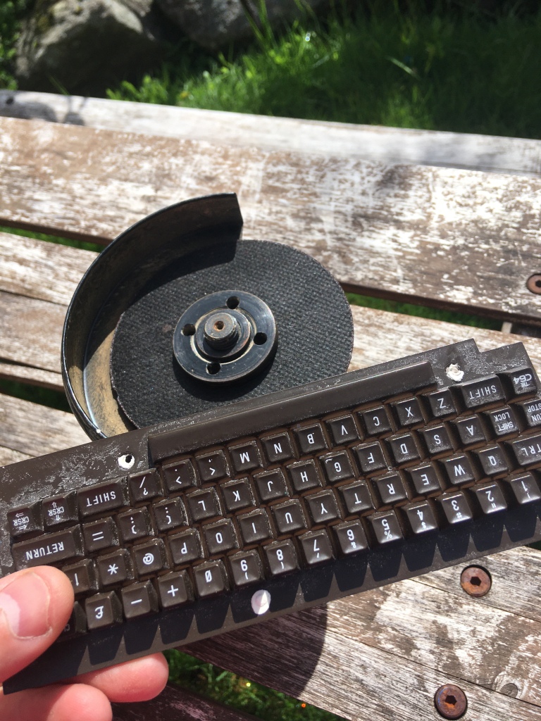
ROUND 1

Mwahahahaha!

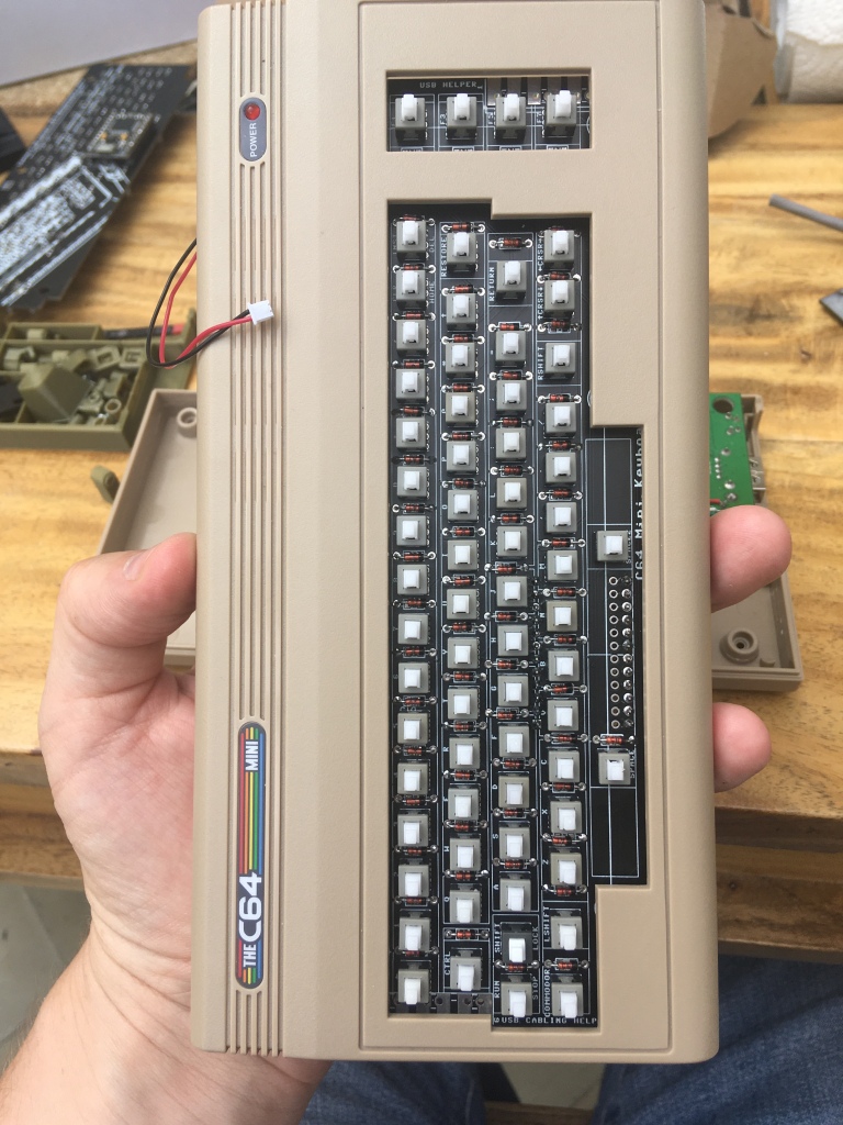
Still not entirely sure if it’s even possible to quickly and repeatedly butcher the C64Mini’s keyboard reliably with good quality.

For doing your own / one off’s, this step, you can take as long as you want. if you plan on doing a few though, taking a day or two individually dremmeling out the keys isn’t my idea of fun.

I do have a CNC – so, worst case I’ll have to learn how to actually use it, then I’d just need to make a protective jig, sit the keyboard on and just CNC the keys out. I’m not really in the mood to spend a few weekends firing that workflow up yet

Failure

The Angle grinder wasn’t really a success…..The blade’s too small and the sanding is going to be too uneven. There’s no way this will work .

Round 2………..

Larger surface area = larger chance of evenness?
Too much vibration

Ok, first thoughts, it seems to work, abeit slowly and with making my hand a bit sore….

new sandpaper should do it

At this point, I figured if I use something soft and large, I could hold the keyboard in place and sand it without hurting my hands so much…..

Puzzled over this one for quite a while till I looked down……..

Found an incredibly inefficient lawn cutting method! – Orbital sanding

Seems to have done the trick!…Pressing down into the grass holds the keyboard in place and also helps resist the vibration of the sander, making it sand more efficiently…………Win Win….Also i’ll patent pend using oribital sanders for domestic grass management.

But……

Poor Lawn

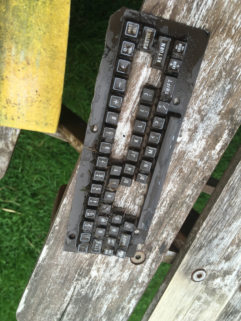
I moved to another bit of the lawn to avoid totally destroying a good bit of the grass…….I found that sanding till you can see the blacks of its eyes…….the lines between the keys seems to work well. At this step, you’ll want to remove as much material as possible to avoid so much processing / sanding later on

Do resist the urge to twist / remove the keys, try to let them come out almost by themselves

oops

At this point I’d realised that an average household lawn is actually quite abrasive..Have a look at the whiteness of the edges of the keys!

Oops! – ah well, this is why i’m experimenting, so you don’t have to. I’m going to run with the theme though -these keys look a bit battle worn now, no going back so i’ll probably add a similar theme to my C64mini case 🙂 will be good to relive the old days of creating scenery and my Warhammer 40,000 airbrushing . never really did play it, just enjoyed hacking up the plastics……..Anyways…

Keep sanding, get as much material off as you can (it will save a LOT of time later)

Once you’ve got them all separated, make sure to lay them all out in order so you can admire all the keyboardy keycappy goodness that’s resulted from the dismemberment of an innocent miniature recreation of an 80’s 8 bit home computer.

Eeeeeeeeeeeeeeeeeeeee

Now, go spending several hours in the garden trying to find the most commonly used letter in the English alphabet!

I’d neglected to factor in the ability of these tiny keycaps to fling themselves a considerable distance in various directions whilst being vibrated several hundred times per second.

Suffice to say, if you’re doing the same thing, try to do it in a location where the floors relatively clean and uncluttered

A colourblind person trying to find a brown keycap in a green lawn that’s not too long, but just long enough to expose the also brown ground beneath……..Yeah, not fun.

After an HOUR of searching though………………..Eeeeeeee….A full keyboard

full c64 mini keyboard keycaps!

Next step – post processing. Removing supports.

This step i’d say is the most important. Sand down a bit the bottom and curves of each key. Get rid of all the burrs, bits, etc. you won’t get much of a chance to do this once they’re stuck. Spend a lot of time on this, cleaning each key, just getting it ‘right’

Mini Mould All filled

Once your keys are all looking great and sanded, smooth – arrange them again into a the keyboard layout. Then, one by one, transfer them into the mould.

you’ll wanna make sure you get this part right 😛

I did them line by line, starting left to right. I also had taken a picture of the keyboard prior to refer to. Check twice, place once……………

Now i’ve realised that I haven’t actually considered how to stick these things in! – i’ll need to go research glue, D’oh! gotta pause this for another week of research and buying bits

C64Mini working keyboard – The Butchery Part 1

Time’s progressing and it’s still taking a long time to obtain a satisfactory print of my CAD keycaps. Some quotes have come in and…they’re quite a bit.

so, time to change focus for the short term to let me actually play games on the mini with all the keyboardy goodness that a working keyboard will allow

So, on to some butchering

The Plan….create a plaster of paris negative of the original keyboard – to hold the keys straight when attaching them.

Step 1 – Print out the case design from my last post

Fits like a glove……..or does it?

Step 2 – realise that I’m making a NEGATIVE and the keyboard needs to sit INSIDE the box, ‘upside down’ Redesign and re-print…

Better

Step 3 – Coat liberally in spray oil… Wife wasn’t too happy that I’d used her pricey artisnal olive oil from our trip to Italy, nothing but the best for my Mini though………

Step 4 – Knock up a batch of pancake batter Plaster of paris…About 50 grams of powder and 60ml water worked for mine….not too viscous.

fill the keyboard case just over 1/2 way to measure what you need

Step 5 – Fill up the mould

Screw on the keyboard – making sure the keys are aligned and straight with the F Keys and wait overnight…

Use the holes either side to top up the plaster so it overflows a little

Give the whole combo a dozen or so short sharp drops / knocks on the table to free up any air bubbles

Mmmmmmm….Keyboard Cake?

C64 Mini – Cutting the existing Keyboard Part 1

Did an attempt at a jig to make hacking up your own keyboard just a little easier….

it’s fairly easy to hack up the existing keyboard into bits….(get hacky thingy, cutty thingy, hack, cut…maybe smooth off burrs if you’re feeling artsy)

Getting the brand new hacked up bits of plastic that once looked like a keyboard to sit straight on the switches and resemble the previous keyboard resemblance …..not so much.

Turns out that making things ‘straight’ is hard……..so, some ideas

3D design and print new keycaps with locking mechanisms that work with my chosen keyswitches (still onging, it’s been MONTHS of work)

My first other idea…….. create a form to fill with plaster of paris, press the plastic full keyboard into that form, leave to set…

Remove keyboard and admire a perfect negative image of the keyboard.

Two things that could be done with this

Use that plaster of paris as a form to create resin keycaps (without any lettering) – I’m working on that!

second – it can be used as a perfect ‘form’ to sit the newly butchered keycaps in, fill with epoxy glue, sit keyboard PCB on top and let the keycaps become glued on, all nice and straight like!

it’s fairly easy to export the keyboard PCB outline from EasyEDA as a DXF then import to Fusion, extrude and…voila!

But…There’s an ever so tiny mistake in the image above

That’s the printed version…The holes line up great!

But….

Yeah, the keyboard should be face down!, D’oh!

i’ll see if the snips’ll work

The other thing….

Fits like a glove….

Nice and snug – Note the top row of keys is level…..

Some small design work needed but the idea has promise!. I just need to re-jig the hole widths a little to accommodate the angle of the keyboard better!

I’ve purchased another couple of C64 Minis so that I can improve this jig more. I’m not quite certain where the keys will ‘fall’ once they’re seperated from the base of the plastic moulding.

The more I think about it, i’m thinking that there could be a shedload more work in this jig – one ‘saving grace’ though – due to the way injection moulding works – there’s a slight taper on the existing fake switches. And, I suspect that the rear of them has been modded so that they’re almost perpendicular to the base. this will help the whole mould ‘pop off’ the injection machine…

That also helps me with this jig as it really means that, at the base of the keys, all the keys seem to have the same uniform rear rising, almost perpendicular taper and front curving taper. kinda like the below diagram

That could turn the whole change into just re-extruding the jig key holes at the 8 degree angle of the keyboard as above……..

A Broken Rice Cooker :-( (3D Printing to the rescue!

Picked up a Tefal rice cooker when living in Australia. They’re superb, reliable and make great cakes

Highly recommend buying one 🙂

Our latching mechanism broke recently, requiring us to jam some weights on top to ensure the lovely cooked rice goodness continued……….

I Gone Dun Fixed it!

I’m getting a little better at Fusion360 now and my work with the C64Mini keyboard taught me enough about surface modelling to knock up this thingy 🙂

The old one’s at the top………the sticky outy bit snapped.

Now, another rabbit hole though……PLA is quite tough

….Until it’s warmed up.

….Rice cookers get a little warm…

It lasted a couple of weeks at least…

Picked up a roll of ABS, first time I’ll be using it, so wish me luck!. Also i’ll redesign those curves just a little better 🙂

3D Printering – The Ender 3 Pro….

Just over a year ago I purchased my Creality Ender 3 Pro…an absoloute steal at about £140 after discounts and Topcashback special offer at the time.

I was having so much ‘fun’ with my Wanhao Duplicator 9 that I didn’t open the box for nearly 1/2 a year. and I only fired the thing up a few months ago!

I have to say, I’m impressed. The printer deserves its rabid fanbase following. It printed flawlessly out of the box without any setting up.

It’s surprising the difference having a reliable ‘work horse’ printer makes to the hobby. I need a bit – I just go print it. no faffing about with levelling and bed adhesion.

Till it doesn’t…….

OOps!

Note, if your previously reliable printer seems to under-extrude, even on known great filament – try the extruder arm.

Something seemed ‘off’ when printing standard stuff – almost overnight the printer just seemed to under-extrude, not be reliable and, well, become more like my Wanhao D9 (a bit crap)

Even bizzarely, the printer would print OK over to the left, but under-extrude to the right. Took an hour to diagnose this! When the head was over to the right – it would pull the mechanism slightly which dislodged the arm enough to slip the filament.

Luckily, This extruder tech hasn’t moved in years…….An unassembled, missing parts kit I picked up off facebook a couple of years ago (syntek, sintek or something similar) which itself was a few years old had just the part..(which complete, looks identical to this Aliexpress one …..

Works a treat….

Except….There’s those new fangled ‘dual gear’ type extruders they’re on about….

and….well, I have a LOT more spares upstairs that i’ve gathered!

And, well, if i’m upgrading one extruder drive mechanism, it’s shockingly easy to add a second….

and…

Fortunately (for the Ender 3) , My Wanhao Duplicator 9 decided to ‘blow up’ a bit *Probably assisted by my dual 5015 blower fan mods

See that Poor MOSFET M3 – Right by R12….

So, now, my D’s guts, kinda look like this……..

What’s best! – I now have a working 3D printer that I can use to print parts for my broken 3D printer!

Wooo

Now, looking at dual extruder mods……… – https://www.thingiverse.com/bleugh/collections/3d-printer-carriage

looks like my tinkering time’s filled up again. gotta get designing a ‘fix’ for the D9…and a dual extruder / colour setup……

£40 well spent and a happy Hamster, a Wheely good use for a 3D Printer

Back a couple of years ago, I lucked out on a facebook marketplace post. Someone was selling an unassembled 3D printer kit, that was tatty and had missing parts………Woo!

I did a 30 mile detour on my voyage home from Wales and grabbed it. excitedly pulling all the bits out of the oversized, filthy box and….Putting them into a rather smaller, cleaner box for a couple of years whilst not doing much with it.

Well, today, that £40 investment paid off.

by hacking a chunk off the 8mm threaded rod, using a few bolts and washers, and a quick mod using a spare Hama-beads square that we had lying around, I was able to fix the broken hamster wheel!

or, in other words, I’ve massively over-engineered a fix by butchering a 3D printer (kit).

On the plus side, I’ve a happy hamster AND saved £2.87 by not needing to buy a new one!

Also, It’s gotten me thinking….HAMSTER STATISTICS.

How fast can they go?, how far do they run?

I’ve just picked up some of these – Hall effect sensors

i’ve already a handful of Arduinos and Raspberry pi’s. ………..

Something Different – a New laptop – Ryzen 4800U – A BEAST

I gone and got me one of these…..

My first new laptop in over a DECADE…

https://www.lenovo.com/gb/en/laptops/ideapad/s-series/IdeaPad-5-15ARE05/p/88IPS501393

A Lenovo Ideapad 5 15″

and it cost me pretty much bang on £500 GBP after discounts and cashback! (Thanks to HotUKDeals – Link here, well expired by the way)

What’s special you ask?, Why now, why not let my perfectly servicable ASUS Republic of Gamers Original I5 based laptop keep ticking for another few years?

Well, A Processor / APU Called the Ryzen 4000 series, codename Renoir by AMD caught my eye back late last year

IT’S A BEAST

I purchased a variant of the laptop with the Ryzen 4800U processor inside.

One of the first things I did was to run a Benchmark – This one

The result – Just a shade under 20,000 CPUMARKS

…………a laptop, costing just £500 outperforming Desktop processors that cost more!

This £500 laptop benchmarks in the top 11% of processors globally! it’s faster than almost 90% of other computers out there……..

And, here’s the Cinebench Benchmark. Note that it’s just above the Xeon E5-2697 v2 which still costs £200 on eBay

The i7-7700K is an interesting one though. This processor’s been a ‘gaming go-to’ for performance and overclockability for a few years now , that’s another £200 eBay processor

Something more modern to compare to?

This one’s 488 in single core and 3925 in multi-core

Go over to the Cinebench website and see –

Sort by Single score – sort by benchmark

The closest intel processors are the

i5-9600K (about £200) at 481

and the

i7-10700k (about £400-£450) at 497

Now for the Multi-core

The closest intel processors are the

i7-8700K (about £300-£400) at 3793

and the

i9-9900K (at least £420 ) at 4914

now, one more set of benchmarks – Here – (CPUBENCHMARK.NET)

Scroll down to 19884 – See just what processors are sitting in the same area – what their retail price was! – this processor sits at exactly the same position as the intel i7-10700KF

A 125W DESKTOP processor that costs £400 on its own on ebay right now. Add all the other stuff needed to make a fully functional PC and you’re getting close to a GRAND on a DESKTOP!

In summary – I’m besotted….This laptop’s happily rendering in REAL TIME what my old laptop took tens of minutes in Fusion360

if you’ve been holding off buying a laptop, you really can’t go wrong with the Renoir series of processors.

and, for games – seems to run Fortnight,Starcraft 2, and a few others just fine at maximum settings! performance apparently is about the same as the Geforce MX250 which isn’t sloppy considering this is integrated graphics and has just a 25W TDP when under extreme performance. The MX250 graphics card has a 25W TDP on its own for this benchmark!

Fawning over, normal service will resume shortly 🙂 – in the meanwhile, ask away any questions, happy to answer them

C64 Mini Keyboard – More CAD

The first mediocre print!

It’s taking way too long, but I think I now have the lettering ‘just right’ – at least on the screen.

This was printed a bit too hastily at 0.08mm layer height on an Ender 3 printer. I’d used a brand new roll of untested filament and didn’t bother changing any settings. – it’s dimensionally ‘spot on’..

I’ve purchased a 0.2mm nozzle for my next trial , it’ll take ages but i’m hoping that those fine details on the characters come out a little better.

Why it’s taking so long……..

I’m learning as I go. I’m ‘tracing’ letters i’m finding on the net, creating them as a new sketch along the whole rows. There’s 4 differently angled rows so each needs to be extruded in a different direction to ‘cut’ the key.

This first run matches the C64 keyboard font as close as I can get. I’ll then ‘archive’ this layout for future use and create a second ‘3D print’ version.

This version will forgo the accuracy of the font and make features much wider, more rounded to allow the characters to come out better once 3D printed. The complex ones like ‘run stop’ won’t ever come out great on a standard filament printer, but the letters already come out pretty good…that’s a win for me!

a full keyboard!

The full keyboard is above – and you can see part of one of the adaptors i’m designing to click them onto the keyswitches. each keycap is hollow. that small grey part will sit inside the keycap

Where the time’s being spent…..

And finally – part of what’s taking so long.

Each key/character is taking on average about 1/2 an hour to an hour to design. Lets say 45 minutes.

65 keys to label

That’s a LOT of minutes…and i’m only getting an hour or two every few nights – a good solid weekend ‘free’ would be great and have this sorted.

On top of that labelling (which is now finished) I have to try to make each letter more legible and easier to 3D print. Generally that means ‘bevels’ everywhere – you can see above that i’ve done ‘Run Stop’ and ‘Shift Lock’ but SHIFT is still to do….it’s not as easy either as ‘copy, paste’ the Shift from Shift lock – that’s a different sized font on a different sketch plane.

Just one example of the issues I’m seeing…The Letter B

The Letter B – trying to create a fillet – rounding off the edges

The Letter B above has an issue with the geometry – just by the 0.1 – there’s a part internally up towards the arrow that shouldn’t be there – that’ll could play havoc with a slicer when set to really small layer heights

B – Alternate view

But, the Fillet also creates a zero thickness surface which looks unsightly and will probably cause issues if I don’t correct it now

So, Back to the sketch

Letter B – The Sketch

As you can see, i’ve kept the characters with few (if any) constraints. this way has been easier to freehand and eyeball as I can drag stuff around till it looks right by ‘locking and unlocking’ lines. most constraints used to create right angles, etc have been removed after to help with the process of making it 3D

Anyways, the ‘issue’ with the fillet seems to be around the place where the two control point splines meet – i’ve highlighted one in blue above.

I re-coincide each spline (have found deleting and un-deleting works, as well as hitting coincident )

That change should hopefully roll back up the timeline to allow me to make the fillet work.

To Create the key lettering I the character by 1mm elsewhere in my workspace, then move it to over the key.

Then extrude the face of the character into the key and ‘cut’ ….

this may seem odd, but it’s a really quick and easy way of consistently creating cutouts on a row of keys and making quick changes later.

That didn’t work, so, jump into surface mode – delete the entire inner arc of the B. Re-create the arc as a ‘patch’. Stitch together the lower part of the B. Then stich the whole keycap, then re-apply fillet and…..Voila…..3/4 an hour later, one filleted B…And a learned workflow if the same thing happens on another key!

Note, as-is, the keyboard fonts are a bit innacurate. I’ve sized everything based upon the smallest characters that need to fit – i.e. run stop, etc. The individual letters could be bigger – but any bigger and they’d look too big compared to those……….

Next steps,

DFM – Design for manufacture.

Just because you design a 3x2mm hole, doesn’t mean it’ll print at 3×2. Generally Filament printers do outer perimeters a little larger, inner perimeters a little smaller. The first few tests i’ve done now prove this. so, After a few months of ‘out of the box working’ on my Ender, I’ve finally gotta bite the bullet and calibrate it. The plan is to create an offset in the CAD file so that I still design the holes accurately based on measurement, BUT, can add a accurate ‘calibration figure’ Fudge figure to make them a little larger or smaller as necessary.

Right now my Printer is doing slightly oval prints – which should be easy enough to sort out if my D9 Adventures were anything to go by

Spectrum Next – controller Board Iterations, 3rd and counting

I Purchased 10 controller boards with the SMT components ready assembled There’s a few small bugs……But, that’s what prototyping is for.

First major annoyance – I’d goofed and left VCC on the arduino as 3.3v in the schematic. so, the board wouldn’t power up inside a next. Quick fix is to short RAW – to the VCC pin on the Arduino

(RAW is a 5V OUTPUT when plugged into USB, or 5 and a bit Volts INPUT to power the Arduino)

This has the potential downside of back-powering the Next via USB via the 5V Line when it’s sitting inside a Next and someone uploads a sketch

Another change needed – The Arduino’s USB port fouls the case when fitted inside. With a USB cable in, the lower part of the keyboard inlay blocks the port. – it’s ‘just’ about bodgeable however if you really wedge it in there. But, not ideal So, i’ve tried with soldering the arduino ‘upside down’ on the wrong side of the board – that seems to work. The board’s mounted just far enough ‘up’ into the case that a USB cable can sit under it.

For the production version i’ll re-arrange the board completely

Another further change –

Removing the RAW pin entirely from the Arduino and shorting the Next 5V directly to the VCC pin on the Arduino

That’s about it for these pictures,

From top to bottom –

Original board – has a resistor bodged in and the RED led installed on the wrong side. Also has my ‘impossible to solder straight’ PCB fingers.

Third board – upside down mounted arduino with missing RAW pin

Second board – my ‘go to’ working one right now – also has the first run of my ‘quick fit’ connectors……i’ve done about 20 cycles of inserting now and they’re still working!

Spectrum Next Blinkenlights…More progress Insert PCB’s and first (second) light!

Now with 8 LED’s worth of goodness!

Due to my previous goof-up of having made the old LED insterts ‘backwards’, I designed new ones!

They’ve arrived and are all round much better

  • Slimmer – just 2.2mm wide
  • 8 LED’s!

Here’s what they look like – the features are a bit too small for JLCPCB to handle on their mass production – their mill uses a 1mm bit – guidelines are minimum of 3mm between milled out slots

I’ve ordered 50 of these – should be plenty to fill up the 10 prototype control boards i’ve gotten made and leave a few over for experimentation / errors

There’s a small problem however with mousebites this small – each board takes a good five minutes or so of dremmeling to get ready!. I can do about 7 boards to a charge of my battery powered cutting tool….I’ve ordered 50 prototype PCB’s so that’s lots of minutes of work ahead! good thing we’ve a handful of N95 facemasks picked up from back in March just as the world went loopy!

Here they are in all their glory, powered up the RIGHT way round on a controller PCB.

I hand soldered all 4 of them using some new (expensive) solder paste,d 3 worked first time! the last one had two LED’s mis-aligned…Quite a good improvement!

Each insert so far on the prototype is taking easily 20 minutes from receipt of parts to working device. Each new controller PCB is taking over an hour of soldering and wire cutting for the quick contacts. That should come down quite a bit once i’ve figured out a process.

First Light INSIDE a Next!

Yeah, spot the mistake 😛 Still, quite chuffed – these are powered up and working INSIDE the next! –

There’s no control YET – this is just a single routine that runs upon powerup in the Arduino….

IT’S ALIVE!!

And, just as a final superb moment – look at these results of a quick i2c Scan (there’s a lot of numbers due to using an HDMI monitor)….That 3rd Device at address 0x45 – That’s the Spectrum Next Super LED Blinkenator 2000 just waiting for a .DOT command to control it 🙂

Spectrum Next Blinkenlights…More progress Inserts

The CAD for the clear plastic parts of the inserts is coming on well. I’ve just ordered a handfull of these to be Resin printed…..

Some extra features –

  • 339 small 0.25mm dimples to help diffuse the light!
  • Strain relief for the PCB – the two slots on either end will help slightly mis aligned PCB’s to sit in the cutouts
  • Much thicker top layer to help with light diffusing

C64 Mini Keyboard – Rev2 assembly

Lovely and sunny outside. I’m in the conservatory kinda enjoying the outside………
Through Hole Diodes should make for an easier assembling kit

My Kids hate me, my wife’s lonely but the march towards C64-Mini Keyboard workery continues – That and they let me have a few hours to tinker on the weekend!

Figured whilst assembling the new boards, I’d see just how long it takes to solder them….

Quite a while as it turns out

1/2 hour to solder in 65 through hole diodes

1 hour to solder 67 switches

another 1/2 hour testing and programming

So, about all up, we’re probably talking 2.5 hours for me to fully assemble one of these…….

Except, that 1/2 hour of testing and programming actually turned into a 5 hour ‘session’ of bug fixing / fault finding – one of which…..

One of these is not like the other………..

A back to front key causing lots of characters to repeat accross the screen…..M, Space – which are both on the same column of the matrix too!

Fixed that and have discovered that it’s not really possible to re-use the switches once you’ve soldered them in – UNLESS you use a hot air gun to remove them. I’ll definitley include a few ‘spares’ in each kit

The next problem – A sticky, grindy P key – I lifted a pad removing it , fortunately, the pad wasn’t electrically connected – only 2 actually are – which will save you some time! – just solder 3 holes for each switch – that’s 201 solder connections for switches instead of 402!

The next problem…the Fantastic QMK Just refused to work and compile 😦

Kept getting “qmk avrdude.exe: butterfly_recv(): programmer is not responding” the thing just wouldn’t work over USB like the others had

which turned out to be a couple of things.

You can’t use AVRDude when the Arduino IDE is open…

Arduino Leonardo type devices (well, the clones anyway) can be a bit finiky with the USB…

Generally sending them a ‘blink’ sketch does the job…BUT, they very often need a quick ‘double tap’ reset pin to ground whilst uploading……..that’s why I have a RESET header on this board – if you want to solder one in, feel free, it’s mainly to help me when developing it.

Another issue was the frequency setting in the rules.mk file – I’d previously used a 5V Arduino pro Micro (Atmega 32u4) , somehow a 3.3v one had snuck into my spares box – these run at 8MHz, not 16MHz

Changed the firmware, recompiled and……..It’s alive!

First row lined up – second just tacked on with a single joint, ready for lining up
Finally added a bit of heat shrink

Straight!, got the technique sorted – Note the two that are slightly ‘off’ to demonstrate what happens when you change the way you ‘hold’ the switches when flipping the PCB to solder

The case fits the keyboard like a glove!

Also got a bit of a chance to progress with the CAD……

This one day may turn out to look like pretty rough keycaps! mini ones! for a mini computer!

C64 Mini Keyboard Progress..

Rev 2 PCB’s have arrived – 15 of them!

Now waiting on enough Arduino Pro micros and switches to start making kits up!

Each DIY kit will probably contain the following – i’ll firm up with pictures once i’m done test populating a rev2 board

  • 70 Standard switches
  • 70 Diodes – Through hole (possible SMT option also depending on price)
  • 1 USB Hub
  • 1 PCB – Rev 2 or later
  • 1 USB cable
  • two small pieces of heatshrink tubing
  • a couple of pieces of wire
  • 1 Arduino Pro micro – Pre-programmed with QMK firmware and custom Keymaps
  • Some instructions
  • a set of FDM – Filament printed keyswitches – These probably won’t be ‘perfect’ so i’ll be chucking them in as effective freebies as I won’t be releasing the keycaps as a digital file.

About that last part – I’ve spent countless hours on creating these keycaps, and still have more to go. I’ll eventually release them as a Digital file, but for now, you’ll be able to at least use the freebies to see if new keycaps are for you.

If you wanted a professionally printed set, i’ll be arranging something with a printing bureau somehow… It’s also likely i’ll be able to source reasonably costed SLA resin prints of these…watch this space

And for the money shots…….I’ve finished the top row of key text!

Now I’ve gotten the first row done, the next three should be significantly quicker.

The text is recessed into the key by about 0.4-0.6mm – between 2 and 6 layers of 3D print, not really enough to be clearly felt – but enough to be ‘seen’

After that, there’s the optimisation for printing – Filleting the edges – trialling depths and generally finding out what actually works, looks and feels good

Spectrum Next Blinkenlights – PCB’s arrived and First Light

A christmas tree creation for a JLC PCB competition

and i’m well chuffed to say – they’re almost alive!

There’s a few teething problems however,

My ‘excellent’ idea as can be seen on my last post – https://bleughbleugh.wordpress.com/2020/05/19/spectrum-next-light-strips-more-first-light/

to use some PCB grounding spring contacts to provide a quick fit connection didn’t really pan out – the contacts simply didn’t solder on easily, too difficult to align correctly and quite weak – I tore a few pads off trying to get them aligned and correctly ‘grippy’ on the insert.

multiply that by 16 each board – the first one took me about 2 hours to get to be in an ‘ok’ state – Not really acceptable for a mass production product – not that this’ll be mass production but I’d rather not spend half a day on each of these getting them ready for sale……..

The second slight issue – See the photo below

The PCB is laid out on top the next board in the position it’ll be installed in.

There’s a prize for someone that spots the goof-up

Have a further look at the PCB powered up………..

First Light! – The board works 🙂

Yeah, I got the inserts ‘back to front’ – That’s the result of working on a bottom mount PCB from the bottom…….

There’s two ways I can fix this

Simply rotate each LED by 180 degrees on the PCB and install a bodge wire to swap the input and outputs around………

OR….

I can simply re-design the LED insert and improve upon it!

a few reasons to re-design,

The first 6 LED version still has a bit of point brightness – I fear that even with the SLA printed inserts it won’t be diffuse enough..

Some statistics

8 LED’s – This should spread out the light more, reducing the hotspots a bit

0.4mm Slimmer – this lowers the LED’s further into the case, allowing much more plastic to sit above. I’m hoping this will de-focus the light more

Reversed connections to match the reversed controller board!. reversed is the new non-reversed now 🙂

New insert PCB’s are on order and should be here in a couple of weeks, I’ve bitten the bullet and ordered FIFTY….Also a few hundred more LED’s and a large tube of solderpaste.

Doing these first 10 dev boards is going to be fun – 320 1.5mm LED’s to be hand soldered!

The Controller board fits inside the case almost perfectly

I’ve slightly offset the J15 connector on my PCB to the one on the next. This offset gives a lot of friction, but needs some long term testing – the standard header I installed on one of my boards seems to work well as a friction fit. BUT, i’m not convinced that 32 LED’s, each pulling 5-20mA, (depending on which datasheet I refer to) – or between 160-800mA total depending on how I end up setting the brightness…..800mA is a LOT to pull

I’ve purchased a new gadget – A Riden RD6006 Benchtop ‘power supply’ so once i’m set up, i’ll charaterise the LED’s and current draw to set the software limits appropriatley

I doubt i’ll take nearly an amp on this board 😛

One further small mistake on the dev board –

That 3V3VCC – it should say just VCC

When originally designing this controller board, I was to use a 3.3v Arduino to make it compatible with the Next’s 3v3 i2c.

For a few reasons, I’ve changed to using a 5V arduino and putting on-board a level translator device – this gives a 5V buffered i2c output that anyone can easily plug into

I forgot to change the net names….The board still ‘thinks’ the Arduino is either powered from RAW (it’s ‘unregulated input’) or 3V3 VCC…

The RAW input drops a few volts through a voltage regulator on the arduino to give the arduino a nice regulated 5V.

The next output is 5V….it’s not enough to power the Arduino through the RAW pin…

Took me quite a while – and a bit of soldering hackery to figure that one out as the speccy picked the board up perfectly when patch wired in place..

USB powered, it works perfectly

in the Next it doesnt….

The fix – I think I can just short the RAW pin to the unconnected VCC pin on this first batch –

and, finally

See that i2c device, found at address 0x45………..That’s the Blinkenlight 2000 PCB :-), alive and inside the Next!!!