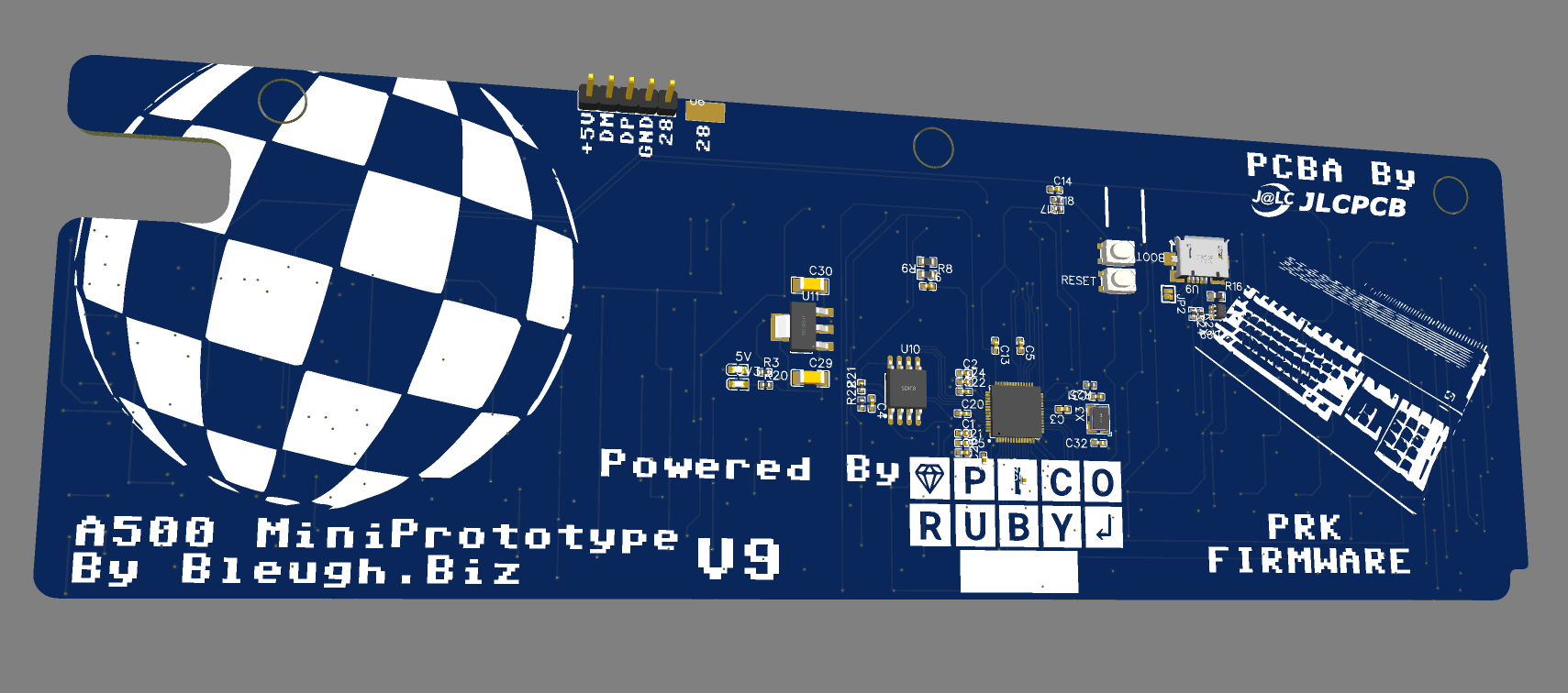
Version 9 – Looks just like all the other ones 😛
Version 9 – Testing for interference fits – the support column is exactly underneath the RP2040 , D’oh!
Continue reading “Keyboards! – Progress on the A500 Mini working keyboard.”
Version 9 – Looks just like all the other ones 😛
Version 9 – Testing for interference fits – the support column is exactly underneath the RP2040 , D’oh!
Continue reading “Keyboards! – Progress on the A500 Mini working keyboard.”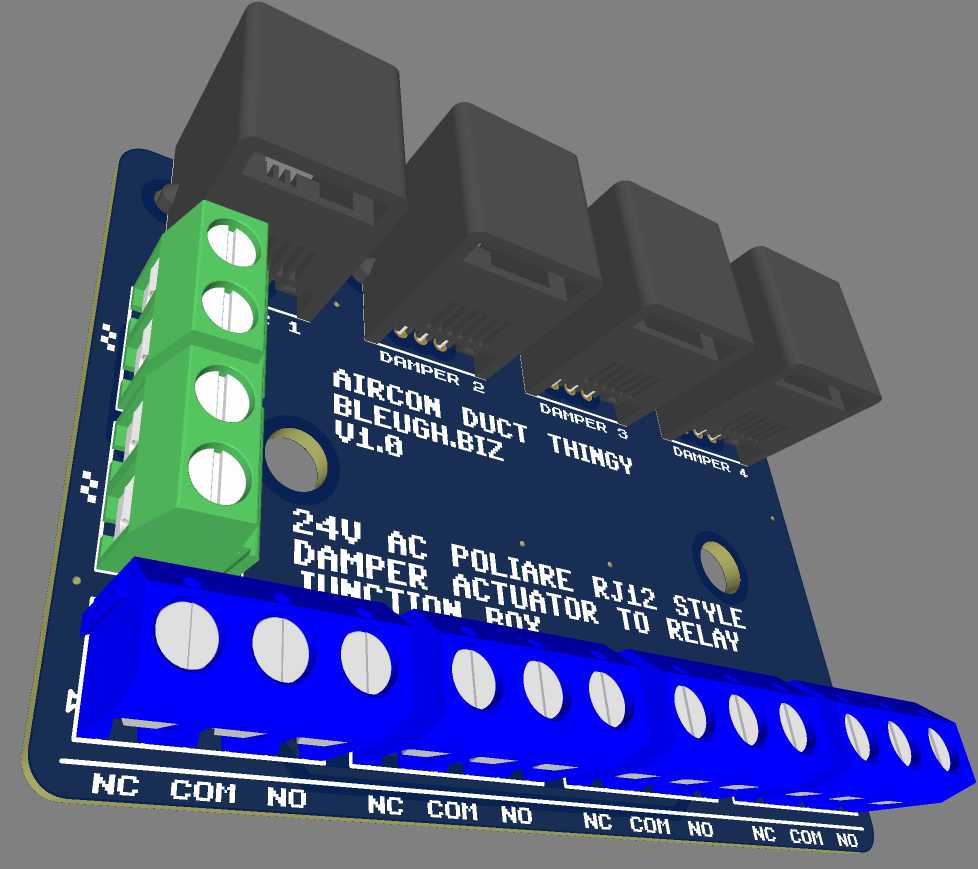

We had an LG Ducted Aircon system fitted in our Australian house back in 2015 – an LG B55AWY-7G6 I believe , a 15.1Kw Beast.
Well, turns out they take a lot of power…

And this is on a warmer day!
With Australian energy prices spiralling ever upwards… it gets expensive to run this. It draws just over 5kW…or, around $2.5o per hour to run during peak hours.
To make things more efficient, 3 zones were installed. Just hooked up to a 3 way electrical light switch, entirely manually controlled.

This isn’t enough zones – our ‘middle’ bedroom gets too hot – this is the outlet closest to the internal Aircon unit
The furthest bedroom doesn’t heat much at all – the furthest.
So, Enter Home Assistant
Normal people would call a professional and get an intelligent home climate control system installed (like This, or This) to take care of the ducts automatically.
That’d be too easy
I Purchased a couple of Zigbee relays
And grabbed a whole bunch of Zigbee Temperature and Humidity sensors
I found some cheap damper actuators which have an annoying RJ12 connection on them, they use internally a simple 50TKyj24-2.5-4700 AC Synchronous motor which has a ‘common’ and two other wires, one for driving clockwise, the other for driving anti clockwise

And, those RJ12’s are the reason for my Adaptor PCB. I need to feed 4 actuators with AC on either the red or the yellow lines, AND have the other side of the AC ‘common’ …it would quite a mess if it were all cabled up!
So, Thankyou to JLCPCB for having such a well priced PCB service.
The other PCB – is inspired by a number of people – https://github.com/Flameeyes/esphome-lg-pqrcuds0/tree/main
https://www.instructables.com/Hacking-an-LG-Ducted-Split-for-Home-Automation/
and the latest one – https://github.com/JanM321/esphome-lg-controller/tree/main
It just converts the LG controller’s protocol into MQTT so Home assistant can make it easy to integrate….Not much to write really, LG’s old wifi implementation (circa 2013/4) is pretty flakey nowadays, this ESP32 based local wifi connection should be much more stable.
Still here, my stuff from the UK arrived so i’m slowly unpacking / organising and building up a workshop to be able to start the fun stuff again.
In the mean time, now we’re back in a house we own, I’m slowly doing some fancier stuff around the house to bring it into the modern age.
First thing – Just what do I use, how do I automate, what can I automate and can I do it cost efficiently…
Continue reading “Home Assistant! – Home automation”Solar was installed today, here’s some relevant technical stuff,
heck, it’s not retro related, but, i’m back blogging stuff again!
The solar system installed is quite simple…just panels, inverters, not fancy optimisers or anything else!
32 x Longi – LR5-54HPH-415M – Himo 5M split face solar panels – 21.8% efficiency!! Datasheet – Here . Website link Here
2 x SH5.0RS 5kW solar inverters by Sungrow – User manual – Here
This all adds up to a peak of 13,280 kiloWatts of energy production split over 64 panel segments into 4 strings into two inverters…a maximum of 10kW of production!
the 10kW limit on 13kW of panels…. well, that comes from legislation here in NSW that allows a maximum of 5Kw generation to send to the power company on a single phase for domestic
Our typical power use is over 5kW at any given point, so, we’re allowed two inverters, one to power ourselves during an average day, another to pass excess energy to the grid / provide more power…I’ve ensured that we have ample space to roughly double the number of solar panels and inverters in the future when funds allow…AND, w’re in an ‘Ausgrid’ region which allows 10kW instead of the standard 5kW…
Another factor in limiting sizing comes from the way our government provides incentives to install solar in zone 3 areas! I’m entitled to 146 STC‘s!! which at current rates gives me quite a few grand ‘rebate’ to pay towards the solar system…


an older pic of the roof
And, a picture of the house roof. I decided against the configuration shown which was done via a phone consultation / internet survey – in real life, it wasn’t that practical..
The roofs have a 20 degree slope, and are pretty much North at the top south at the bottom…And, every PV user knows that solar panels should face the equator…So, at least in the southern hemisphere, south facing panels aren’t the ideal situation.
I requested an installation of 16 north facing panels, 16 south facing. (cue every PV armchair expert screaming WHHHHHHYYYYYY)
Well, here’s why.
Back in 2015 when we purchased this place, we had a lovely northen facing roof with several kilometers of thin piping sat on top providing solar hot water (not unlike this –

The neighbour sold up and the new family decided to build a 3rd story….which blocks most of the direct sunlight during winter on all but that top row.
shading is a bad thing for solar panels. One long ‘string’ of solar panels will reduce its entire output, from all panels, even if only a single panel is shaded!.
shading is why people go to the expense of using micro-inverters or DC optimisers , people even argue which ones are best.
Well, those things cost real money, and add more complexity. They have to be installed ‘at the edge’ near the solar panels and, here ,down under when the ambient air temperature often sits in the mid-high 30’s, and on occasion in the 40’s…Putting complex electronics on a black concrete surface in direct sunlight is a bad idea..My day job often involves putting electronics into poles, those things get to the high 60’s internally!
So, lots of extra money, cost complexity to re-gain low double digits in panel output efficiency during shading….OR..just shove more panels on!.
Think about it , I decided to spend around $15k AUD to get 32 panels….maybe if i’d added 32 off $200 inverters, I won’t lose 50% of the power during the day…Yep, $6.4k of electronics will mean I just lose (say) 2 or 3 panels (10%).
Better still, those ‘fancy’ panels I’ve had installed are ‘split face’ – or really just a single panel split into two smaller panels, but tied together. This means when half can be shaded, it’ll still generate full energy from the top half that isn’t…thus not dragging down the whole string quite as much…
Or, to summise. I could spend about half of my 15K budget to roughly half the panels, but they’ll have a 40% increase in efficiency during the winter when they’re partially shaded and be more likley to fail quicker…..Nah
Instead, why not spend most of the budget on fancy solar panels that during peak ideal summer generate twice as much energy, but in high winter, maybe only half. I’ve got ample roof space, so the decision was a no-brainer
AND…more solar on the roof reduces heat getting though the ceiling into the house!
One final benefit of having an over-sized solar system, the ‘Feed In Tarriff’
Here in NSW, we get a (paltry) 7.5c per kWh fed back into the grid . that’s free money really!. If i switched off the entire house and generated 10kWh of electricity, fed into the grid for 10 hours a day 365.25 days a year, I could pay off the $15k in under 6 years……
Given that we’re heading into Autumn here in the southern hemisphere, i won’t know how much power the solar will generate at high noon during the summer solstace (nearly 12.5 hours of sunshine!)…i’ll find out next year
Add 13.6 kW of solar panels on the roof!


I’ll detail more about the system and some numbers in the future, but I saw it as a simple choice,
Pay energy bills at XYZ per month
Or, pay an identical repayment on a small loan at XYZ per month.
Really, the math is that basic.
We don’t have a battery, so will have some energy bills, but switching everything to Time Of Use (TOU) will mean we can shave at least 75% off our energy use by simply not using tumble dryer at midnight, or not heating water automatically after sunset!
We chose to pay a $3k deposit to make the math work out such that our predicted energy bills matches the loan repayments…
Anyways, enough waffle, stuff should arrive early next month, then I can really start playing and getting back to Amiga / speccy thingies
Bought a new fridge freezer.
Measured it, should have at least 6mm on each Side to fit the thing
It didn’t fit – note to people renovating. 80’s houses have wonky walls!!
Well, it almost fit…but only at an angle and clearly needed just a few millimeters more on each side.

So, I did what any sane person would do….purchased a circular saw, dismantled this part of the kitchen and cut 35mm off the side!
Continue reading “Back to Oz and home Renovation”A quick post to say, i’m still around, and will be picking up where I left off soon.
Oh, also, i’ve changed countries, back to Australia and to a small town north of Sydney.
I’ve added some waffle after the break,
Continue reading “6 Months later after a pause..some waffle..”I’m a parent of two primary schoolers and for fun, sponsored the publication to do my bit to raise money for the local schools.
If you’ve read the advert and wondered WTF?, just know that there’s a Middle Aged bloke, sat at his work desk, giggling like a schoolboy just thinking about how many people are somewhat puzzled right now!
I mean, who hasn’t wanted to write a silly word in large text, (Verdana, Bold) in a slightly posh publication that gets read by several thousand individuals in Cheshire :-p
The word ‘Bleugh’ originated from my reading of the Beano comics back in my youth.
It’s something Dennis the Menace (and others) said regularly, for various reasons, one of which was disliking fish fingers in school dinners!
I’d no idea how it was pronounced, thought it was funny and have used it ever since.
Though, do note, a few of the websites out there have cybersquatted various domains and are nowt to do with me! Bleugh.biz and Bleugh.co.uk are mine.
That’s it, the story of ‘Bleugh’ used by me as a written pseudonym for around 35 years!
.
As for its current use, it’s a bit of a blog. I’m making and selling small keyboards and various, mostly retro computer related stuff. Maybe one day I’ll grow it into something larger , for now it provides ‘beer money’ and a focus for various hobbies and learning how to ‘make stuff’.
.
If you’re a bit of a nerd, have fond memories of the Compdore 64, Sinclair ZX spectrum, and live nearby, get in touch!
P.s. Thankyou for the teams for putting on a superb School ball, apologies for my terrible dancing!
.
Also, join in, help out your sons / daughters schools, they all need more volunteers and hands on to help with all the special activities that your kids do in school. It would be lovely to see new faces dragging tables, serving burgers, cleaning up!
.
.
.

A while back I managed to snag a ‘Super early bird’ for the Creality CR-Scan Lizard on Kickstarter (there were some legal issues ) – the kickstarter is no longer active, and you can purchase them online .
Needless to say, I got a bargain!.
The original software that came with it was ‘crap’ and I struggled to get any scans out of the thing. But, an hour ago, I downloaded the latest version (from here )

and, ten minutes later, after two geometry and 1 texture scan merged, I got the below! – woo

Having an accurate scan helps a LOT when recreating things in CAD. Yes, the switches don’t look great, BUT, they’re 7mm squares – what I’m seeing, for the price I paid is, frankly amazing, AND, there’s quite a lot of improvement to be had.
So, next steps – Scanning larger things, and instead of working from photos as a canvas, I can use the original 3D item to create the angles! it’s going to be an interesting few months

That was quick! – It’s amazing what’ll come to you at random moments.
I was looking at some uneven fitting panels on a car earlier today and wondered, ‘why can’t the gaps be smaller?’ –
Well, my first idea is to simply see what happens when the gaps between the keycaps are smaller……..
If there’s no room for keycaps to wiggle, they won’t wiggle! – that’s the theory anyway – Prototype is on the printer as I type.
If this ‘rough and ready’ bodge works, I can knock out a more elegant solution that’ll look much better :-), it’ll involve going right back to the beginning, but…ho-hum, such is the nature of product development!
The idea is currently on the printer! – this is a ‘zero cost’ solution that may reduce keycap wonkyness to a level that’s acceptable.
The next idea introduces double the 3D printed parts and some extra parts on top of that – BUT, it’s still a very cheap solution compared to the alternative…..
Have been steamrollering ahead with the keyboard, and making rather good progress – Except for this little annoyance……..

It’s annoying enough to me , and a couple of trusted others to put a freeze on this method of doing things – and to invest more time doing something else!
The problems i’m facing….
The keys rotate around a bit – which, frankly, to me, is unnaceptable.
The GOOD news –
I have a way to IMMEDIATLEY fix it, Different, more expensive switches- BUT…it will increase my COST by 400% – meaning this product needs to sell for around the £70-80 mark, which I feel is waaay too high.
I do believe I have a few other good ideas which won’t cost so much, but need quite a bit of development. I’ve gotten the keys to print superbly and quickly on the printer, so I can work to good, tight tolerances. I can iterate quickly!
SO, it’ll take a couple of months longer than intended, no worries, worst case, i’ll do a limited run of expensive boards…and a wider run of boards with keys that rotate if there’s a demand (I really hope not)
….and, already there’s a small electrical issue!
But….they fit perfectly, everything looks fab!
Now comes the long process of test and tweak 🙂

The picture shows the three PCB’s and the 1 3D printed part inside the A500 mini.
Also shown is the A1011 mini which contains a single PCB and 3 3D printed parts.
And finally shown is the floppy disc, which is going to be two 2D printed parts, one 3D printed part and a single electronic component!
Phew…..it was only supposed to be a small single PCB keyboard kit, that’s feature creep for you
*disclaimer, it may also be able to be a single PCB kit to save people ££, other PCB’s will be options to ease installation and add features
This one’s been nagging away in the back of my head for some time now…I Always wanted one of these containing a hard drive when I briefly owned an Amiga. This is a GVP HD+ / HD8. and maybe a few other products also. This design really struck a chord with me when it continued the Amiga 500’s contours rather than just shove a box on the end.
No idea what I’m gonna use this for – likley a USB hub or ‘something’
This’ll need to be printed to ensure everything aligns, some of the proportions don’t look right – but seem to measure OK.


Prototype PCB’s will be here late next week 🙂
So, whilst waiting, I’ve been playing around a little with the CAD and the ‘extras’ for the keyboard kits – the Real Mini 42″ scale floppy disc.
The cocnept is – to have a ‘working’ floppy disc that you can play games off.


Still some work to do optimising, but i’m rather happy with this second attempt at printing. The metal part has been cut out on my KNK ZING vinyl cutter and has been extracted from a projected sketch.
That works for the Amiga side – But, people will need a way of getting the games onto the floppies , so – Early days yet, An External mini floppy disc drive for a PC!

Cutaway view

This was surprisingly quick to knock up . I found an image of an eBay sale, imported as a canvas, ‘traced the canvas’ and set the scale around the floppy disc slot. I’ve never owned one of these so had to work from many pictures. Still a lot more to do, but fundementally, i’m keeping the exact same PCB’s and mechanism / holder that i’m creating for the A500 Mini. Just putting it in a shell and using a different USB cable….
I will be releasing the design files publicly for this thing so anyone can print up / adjust and make their own ones as international postage gets expensive for things larger than 25mm high here in the UK…I’ll also offer up these for sale with keyboard kits
And, if you’re wondering, just how many picures…and files needed to create a floppy drive and disc…….Here’s a quick snapshot of my A500Mini folder – just for the floppy! and these are the ones i’ve kept for now….


I had somewhat of a PETSCII induced fever over the past few weeks, one that needed Sating before I could practically start anything anew, or even continue anything existing……..
So, when I (eventually) re-make the C64Mini keyboard kit to be less soldery, more easierer and betterer, It may well have PETSCII on those keycaps, for all your milliputty smudgery into-ey goodness!
A500 Mini Prototype 2 is in the post, Every C64Mini keyboard kit and parts have been posted – I’m finally fully up to date!
Three PCB’s are pretty mich ready to go . Just last minute checking, double checking, triple checking needed!.
I’m lacking lemmings on most of the boards, but be assured, there’ll be a few on the production units.
I’ve also now pretty much finished the keyboard CAD…Had to do yet another iteration to allow for the new switching mechanism i’m using..It’s really been a case of design, print, test, iterate, repeat!…Still ‘a few months away’ as always, Real life is taking over a little, meaning less time to perfect this lot.
On the plus side, I really do think this Prototype 2 will be ‘good enough’ for general testing and useage. Everything after prototype 2 will be geared to making it easier to install and add (or remove) extra features. Lots of pics after the break……………..


Made loads of ‘progress’ on the A500 Mini keyboard!
Yesterday evening was mainly procrastinating and playing around with Printed Circuit Board silkscreen / soldermask / copper to optimise the speed at which in could display many sprites simultaneously.
The result of too many hours.
Have a Lemming!!

I’ve tonight finished routing the new PCB and switches!
A lot of work has gone into this! It’s got some ‘extras’ , it’s also an expensive board at 4 layers , 1.2mm thick and nearly 100 switches!
I’ll get to designing the other 2 or 3 (maybe even 4!) PCB’s needed for the complete setup, then place a single order for them all, so it’ll be a few weeks till I can test this beast out!
If they work, Ill make few ‘special limited edition’ early ones to send out, I’ll not spoil the surprise extra features till they’re in my hands!

Well, that’s a wrap for idea 1 – concept was ok enough, but…it’s no-where near good enough for a production run.
After half a dozen trial prints and practice fittings, I’m heading down another path.
The Many faults include
Keys fitting poorly to switches.
Keys not fitting on switches straight
Keys just not fitting onto switches at all
The attached picture sums it up really.
All is not lost however. This is something I had to trial, if it worked, it would have been cheaper and awesome.
I have a few ideas up my sleeve…My next option is right now, considerably more expensive, but has been underway for a few weeks now, I’ll reveal a bit more once the process is done.
On the plus side, the keycaps look great in Amiga Beige! – I’ll work on the darker caps another time.
The PCB layout works great, firmware works, so, really, it’s down to the thing that always was going to be an issue, the switches!
Nearly two years ago, I purchased a rather nice laptop – https://www.lenovo.com/gb/en/laptops/ideapad/500-series/IdeaPad-5-15ARE05/p/88IPS501393
A Nice Lenovo 15″ beastie, with a Ryzen 4800U
I blogged a bit about it right – HERE
Just after Christmas, one of the screen hinges snapped – I had a quick google, then really did nothing – I found thhis bloke –
and, this video
https://www.youtube.com/watch?v=jQ3YShJosio
and, as the laptop was functioning ok-ish, I dismissed it – it was robust enough to use, and wasn’t properly broken….
…Until it was – (properly broke
A couple of weeks ago, both hinges just failed, leaving my laptop screen ‘dangling’
So, I googled again, discovered that I’m not alone. Most people seem to jab a bit of JBweld in and hope for the best
https://www.bogleheads.org/forum/viewtopic.php?t=369644
I didn’t have any JBweld.
I Did however have the following items, which, after years of desperately needing a project to justify the purchase have Finally come in useful and saved some cash
Ingredients
……. a Portable Dremel thingy,
a wide collection of tiny drill bits
boxes of tiny screws and nuts.
A ridiculously small adjustable spanner on my car keys
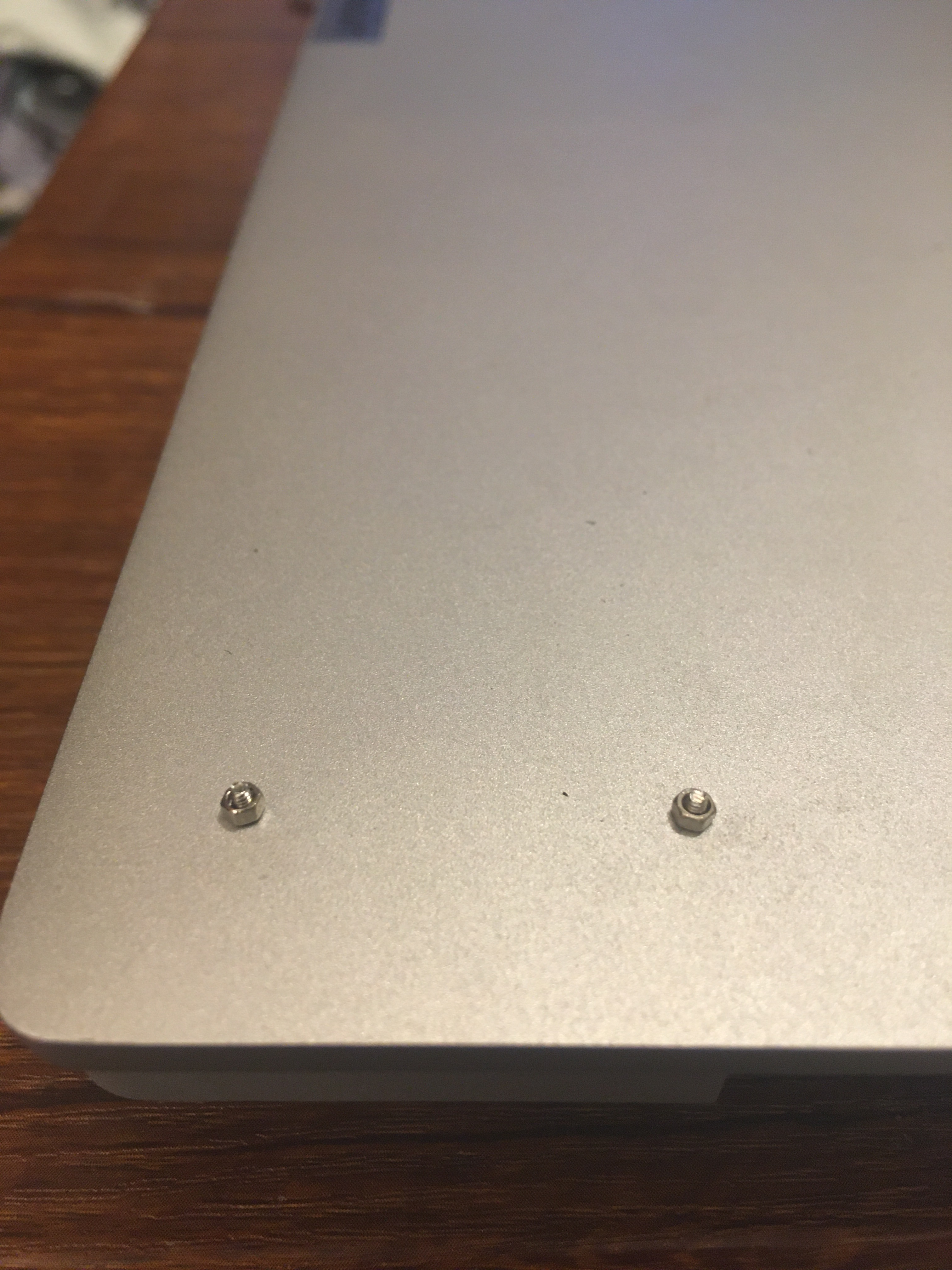
Now My laptop no longer has a non-functional Hinge
Have a small Montage of pictures


To Be fair to Lenevo – they’re extremely responsive for customer support. I can not fault their technical team, nor their customer support team, pro-active calls, checkups and emails, all in, a 5* Lenovo response…..
with one caveat, My laptop’s out of warranty. Still, for most, a quick hundred quid ain’t too bad a price to fix a £500 laptop properly!
First working keyboard keycaps are off the printer!
Only this bit to show as most of the print failed 😛
Well,, 3 prints failed, I’m trying to learn how to use my Photon Mono-X, so far mostly unsuccessfully, these were printed using a known good combination of Photon Mono and Commodore Brown resin 🙂 ….and still it partly failed!!

Next, I have to optimise the design for printing.
I’d added some features to make them work better, but, those features don’t translate to printing very well, D’oh! (That’s called not doing Design For Manufacture!).
Resin printing can be a hard beast to tame, especially when printing 94/98 individual items (98 if I can two keyboard types!!)
This first print is literally an ‘auto supports, Jab a few extras on, hope for the best’ quick test to prove the mechanics.
When the design is finished,
I’ll need to spend a couple of solid DAYS (maybe a weeks worth of evenings) adding thousands of supports MANUALLY to ensure every keycap comes off the print perfect!
That sounds a lot, but printing a single item is different than printing the same item hundreds of times, so it’s really worth the up front investment in time.
And, speaking of time, I’ve just clocked about 600 hours evenings and weekends, on this project now 😛
I’m rather happy otherwise, next week, I should have a full working keybaord to demonstrate 🙂


And, the reveal, part 2

Along the way, I’ve been tweaking some other bits – The Real miniature fake USB Floppy disc is progressing nicely

IT FITS!!
I’m on the second design of the 3D Printed insert, this will hold the USB PCB and also be the interface and guide rails for the floppy.
I’ve also received my memory solution for the discs, it fits superbly! – it can be seen in the badly printed / broken green area. The dimensions are exactly the same as the 3D print i’ve put in
I’ve also purchased some silver brushed effect sticky foil so I can re-create that beloved silver cover….and even have created the label ready to cut out on my dusty KNK ZING vinyl cutter thingy. Hopefully I can make the adhesive sticky enough!


I’ve also started stocking up on Printer resin, ordered a load of sample parts from Aliexpress, test fitted PCB’s…..started on box design, started tweaking firmware, there’s dozens of tasks to do!
Quite a lot of progress, but it doesn’t look like a lot of progress.
Firstly, I’ve had to re-do most of the keyboard CAD – I simply didn’t like the ‘blocky’ effect of the wider topped keycaps I’d created – as you can see below they look a lot more square in real life than they did in CAD…
I’ve now clocked well over 200 hours developing this set of keycaps, likley there’s going to be tens more tweaking / optimising!

So, along with the less blocky (more slopey) keys, I’d discovered my workflow in CAD had created tapered keys – the tops when viewed from above look like parallelograms, wheras the original Amiga had more square keys – it was quite a lot of work to alter this – see the parts below by the red arrows – the bottom bit is in towards the middle more than the top bit.


Have been tweaking things over and over, I’m now finally ready to…….


I think there’s going to be a few people out there actually using this keyboard in anger, so i’ve widened the keyswitch tops a little and added larger fonts to make it easier for someone to fill in some colour if they chose to do so.
Some other progress –

The Floppy Disc insert! – a FULL scale floppy disc fits well

I’ve refined the floppy disc insert thingy – I really think I can make this work – lots of parts on order so i’ll iterate this design over the coming weeks. I’ll do the first prints of the plug in module soon

Speaking of prints….


I knocked up a few of the mini-Floppies. Printed in various orientations to see if it’s even possible to do these. The best print is the angled one..Turns out, it’s going to be tricky as can be seen from the various failures above. Have re-designed a little and will run off some more sample prints soon. The supports on this one will be critical and hopefully not so wasteful as the C64mini keycaps were.
And, almost finally –

Here’s a collection of ‘stuff’ rendered so far. The Keyboard PCB is unfortunatley upside down – due to the way I started modelling stuff, no big deal but makes the renders look odd. The case slopes don’t need to be modelled (at this time) so i’ve just left them flat for now.
There’s loads of parts waiting to arrive in the post, but there’s also loads I can be getting on with, not just on this project, but on numerous others also!
I’ve spent a couple of days designing, and and a today, spent nearly a hundred quid at JLCPCB ordering a bunch of prototypes


I had to bite the bullet and spend some money as I now need to move on with the Keycap CAD. I have a big concern about the fitting of the printed keycaps onto the smaller switches. I’ve gone with ALPS switches as they used to be a huge brand name back in the day and i’m hoping should provide some consitency.
The prototypes will help also to test and develop the PRK Firmware i’m planning to use.
The ‘Clamp’ adaptor is fairly non-functional. It has a Rasperry Pi Pico footprint onboard and a 40 pin FPC style connector to act as a ‘stand-in’ for the Raspberry pi Pico which is currently on the back of the main PCB.
The whole idea of the ‘clamp board’ is to allow an ‘ease’ of installation – I’ll use some Pogo Pins to sit on the test pads by the 3 USB sockets on the back of the A500 Main board.
The plan is to have a basic matrix keyboard PCB, which connects to the clamp board via the 40 pin FPC.
The clamp then accesses the USB and hopefully it can all be fairly easy to assemble.
I’m also testing the Fake floppy connection with the clamp board – no idea if that’ll work or not, we’ll see.
Now the long-ish wait for Aliexpress to deliver my connectors, pogo pins, and a couple of weeks for the Cheapest post option of JLCPCB to ship the assembled keyboard! – nearly 100 switches and diodes on this one, those can be automated in assembly. I’ll need to hand solder on the rear the FPC connector but those are easy enough!
This one’s a good ‘un
Progress to date has been surprisingly quick – most of the ‘easy’ stuff is now done and I’ve added some extra functionality. Most of the research is now done – have spent waaaaay too long googling connectors, Pogo pins and component types / dimensions.

My workflow generally is to eyeball, sketch, measure, adjust….Then when it’s close enough, i’ll print on paper, adjust in CAD, print again then………3D print

I’m quite chuffed – the first 3D print seems to fit reasonably well! – there’s some adjustments needed, mainly the top of the keycaps are a little too wide, but overall for a first run, not bad.

To work out a PCB outline, I’ve scanned the A500 Mini on a flatbed scanner and trace around the important parts, measuring many with calipers


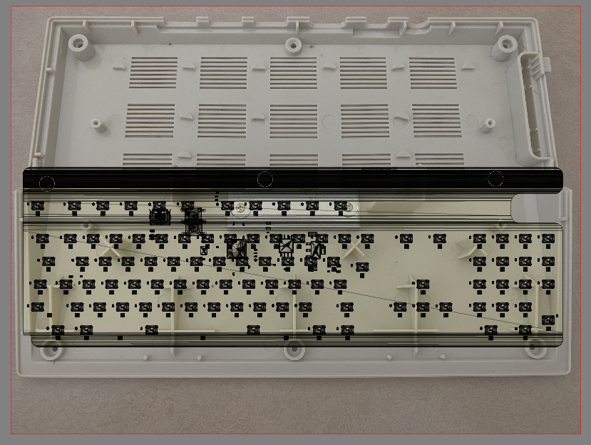
Before I 3D printed the sample, I put the A500Mini on a flatbed scanner to match up the holes – as you can see, it’s pretty darn close! – you’re seeing a canvas underneath the actual CAD model of the keycaps in Fusion. The Enter key is black as i’d discovered a slight profile error, so spent half hour correcting a 0.2mm height error 😛

During the design phase, there’s a process of discovery. My main discovery for the A500Mini keyboard was that….I’d possibly need TWO PCB’s!!
If you look above at the underside of the keyboard you’ll see that there’s no space on the top for electronic components! The PCB needs to mount entirely flush to the case of the Mini. This means I’d need a PCB assembly service that can handle double sided boards (a possibility) – And to also consider a two PCB solution. There’s cost and ease of install considerations for both ways.
The A500Mini has a number of test points on the back, I think using Pogo Pins I can maybe make a clip-on PCB that can securely tap off the USB test points, meaning, a solderless install! – hence the upper white PCB that sits in place of the A500 PCB above
And, now I believe I’m going to go with a THREE PCB solution…….because…

the one with the holes in sits above the stock PCB


I saw a few posts on facebook linking to a guy that’s made a ‘fake’ floppy insert for the A500Mini – https://www.printables.com/model/170947-amiga-500-mini-a500-mini-mini-floppy-disk?fbclid=IwAR3if5FRp3opclhKoTyrkUe63XQtRW-mckg2ymWSKKi1cZvSk1KuRRkzmR4
I figured I’d go one better and make a REAL fake floppy disc. and, the best thing, after several solid days of research and CAD testing, I believe it can work 🙂 – it’ll only need two small cuts inside the A500 case and be totally stock outside. there’s a little more tweaking needed for the floppy disc design to make the MicroSD slot more elegant . I’ve ordered a whole bunch of parts to physically trial this and see if it’s viable.

So, Summary. Still a long way to go, the Keyboard itself is the priority here, the ‘floppy disc’ is just a whimsy on my part for the time being, its development is secondary and may not even make it to a real release if it’s not robust enough.
Keycap CAD – Cosmetics finished, Just needs the ‘switch’ solution figured out
Main PCB – Outline finished, needs routing, quick job to finish
Secondary PCB – Outline finished, needs routing and Pogo Pin solution testing
Tertiary PCB for the floppy disc connector – Concept – parts ordered
Fourth + Fifth PCB’s – the floppy disc itself – parts ordered.
Firmware – Standard keyboard layout is done! – Just needs tweaking and testing on a real A500 Mini
I received yesterday my A500 Mini! – Haven’t even powered it up yet 😛
My assumption about the 43ish percent scale was about right – and the work i’ve done so far on the PCB pretty much stays the same – which is a relief.
However, till now i’ve been using a full sized Amiga 500 to infer dimensions. I can’t easily do that going forward as the scaling factor for the Amiga is ‘a bit weird’ – I think I can see why it’s been done, but, it’s far far easier to re-start the CAD from new…or at least shift the fusion timeline back to the beginning and see what i can recover 🙂
Much more to do, will update later as there’s also a few ‘gotcha’s i’ve found, and a few ‘woo’ moments also!


Heavy on the Photos this post is….
Last year, I needed to scratch an itch…so I spent over a thousand hours developing something

Had a major ‘procrastination’ research binge over this past week, trying to figure out just how I could cheaply and reliably get 3D printed keycaps onto tiny switches.
I’ve found I think two ways that can be successful.
The first – a small tactile switch, with an ‘oval’ or keyed button. The A500mini’s keys are probably just over 7mm square, I can’t use the 6mm switches i’ve previously used as there’s not enough space.
Something like the below could do the job – it has a slightly tapered switching bit in the middle, so I can do push fit keycaps that should grip on. it’s also 5mm on a side, and 3mm on the other, this frees a huge amount of PCB space up, BUT, it’s still quite ‘large’ and the top isn’t tapered as much as i’d like. visually it looks fine, but datasheet suggests it’s straight

There’s also an older, more ‘retro’ type of approach. So, i’ve gone and knocked up a very rough CAD drawing – it’s innacurate, until I get an actual A500Mini in my hands…

and i’ve gone and emailed half a dozen companies to request some MOQ’s. and some pricing!. I’ll fill this in later with more specifics
In other progress – the A500Mini Manual is now available – and, the Keymap is shockingly simple 🙂

So, that means getting firmware working should be a breeze.
There’s becoming quite a few ‘RP2040’ public circuits available now, so that part’s done and dusted on my PCB, all i’m really waiting for is to get some accurate measurements so I can knock up a prototype!
