
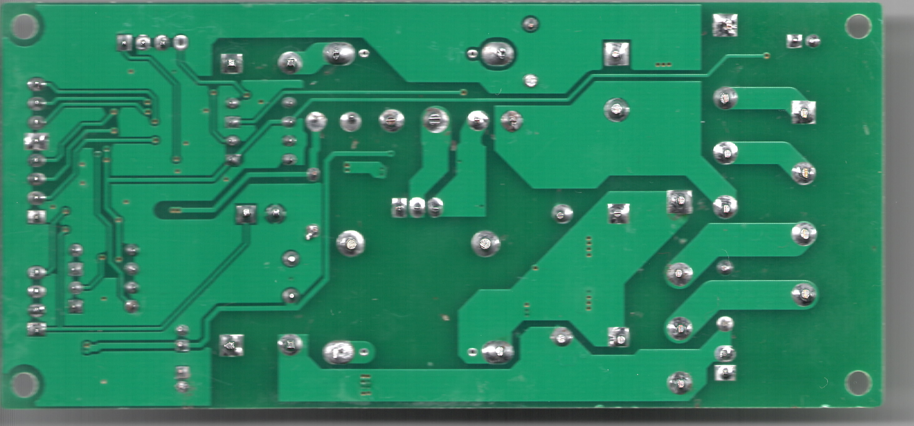
Noting some of the ‘stuff’ on the board, we can see that it’s quite simple really, it’s a small microprocessor controlled, dual sided PCB Two voltages – 18V AC and 36V AC from the secondaries of the transformers, 18V dropped down to 5V to feed the processor electrics….. 36V rectified to DC, then passed to the spindle somehow the micro takes in the variable resistance from the POT at the front of the box and converts it to DC, PWM at whatever voltage the 36V AC is converted down to. Not sure what the extra plugs do yet though, i’ll keep adding to this board STC 15W408AS –
- SOP16 – Single Chip Micro – 8051 based – 8-12 times faster than standard 8051
- 8K RAM,
- 512 Bytes SRAM,
- 3 Channel PWM,
- 10 Bit ADC,
- 5K EEPROM
- UART
- SPI
- 5 external interrupts
- 2 timers
- comparator
- internal clock
- encryption
- RS485 Control
Page 68 onwards of the english PDF datasheet covers this IC, LNK 306DN – AC TO DC CONVERTOR – DATASHEET HERE – 8 PIN IC WITH PIN 3 MISSING IRF 640N – IOR P447D – 5TH Generation power Hexfet MOSFET – DATASHEET HERE KBJ 1510 – Bridge Rectifiers – DATA SHEET HERE 78M05 – 5V Voltage regulator – DATASHEET HERE EL817 X 4 4 PIN DIP PHOTOCOUPLER – AKA OPTOISOLATOR – DATASHEETS HERE ES1J X 3 – 1A Ultra fast recovery rectidier – DATASHEET HERE

There is a few versions of this board around, one older one seems similarly laid out but based upon a 555 timer! Theres a fellow Aussie doing much more digging than I at this time, ill pinch some wording from his page on how my board works. The spindle speed control works by passing the PWM through a low pass filter, then reading the DC voltage produced on an analog pin of a PIC micro. The micro then reads the value (most significant 7-bit’s of 10 bits), and sends it to a digital pot. The digital pot contains an 8-bit data register (16-bit really with command byte) and is 10K and we need 5K, so that’s why we are grabbing 7 bits (need 8 bits and grabbing 7-bits divides the value in half). The last log explains why I need to convert PWM to a resistive value (voltage divider). I’ve also added a feature for the Z auto level probe on the board. The issue there is, my system has been configured to work with Normally Closed limit switches and the act of probing, is a Normally Open operation. Have look at his projects on Hackaday.io Here

Hey, bit of a correction, the section you’ve quoted from my hackaday.io page is referring to how I proposed to enable software speed control with an added external PCB board (I was going to make it, not sure if I still will). I’ll give a quick explanation how the JP-1482 board works. On the STC15W408AS micro, a voltage divider is connected to the P1.0 pin (a ADC input pin). The front pot adjusts the voltage dividers voltage and that is read into the ADC pin. Based on the voltage seen, the STC micro outputs the PWM signal with a corresponding duty cycle on the P3.3 pin. When 0V is seen (pot is at 0 ohm) by the ADC, the PWM duty cycle is 100% (as seen by the MOSFET, the signal in reality is inverted) and when the voltage is 1.7V, duty is 20%. Voltages higher then 1.7V give a 0% duty cycle (the spindle is off).
The spindle motor is powered with the 36VAC from the transformer, rectified to roughly 50VDC. The same 50VDC is passed through a switching regulator (LNK306) to make 12VDC. The 12V is used to drive the gate of the MOSFET (which switches the motor on/off). The 12V is also passed through a 5V regulator (78M05) which powers the STC micro. The a EL817 opto is used as voltage translation, as the STC micro needs to send 12V to the MOSFET’s gate to drive the motor.
The optos are also used to accept external signals from the parallel port.
The spindle switch at the front of the controller box sends a logic low to the STC micro on pin P3.7 through an opto when the switch is swiched on.
Also the external PWM input signal is passed through an opto, then the square wave signal is passed through a low-pass filter to create an analog signal. The analog signal then goes to the P1.1 pin to be read by the ADC. This feature does appear to be disabled though.
One opto is also used to send a analog signal back to the micro (P1.2) which represents the current running through the motor. I assume this signal is used in a over current detection feature.
The 18VAC from the transformer is used to power the stepper driver board. This 18V is rectified to about 24VDC and fed to the stepper driver board. The 24V is also used to drive the fan in the controllers box.
In reality the voltages from the transformer are a little higher. This may be because the transformer was designed for 220V? I read 39VAC and 20VAC on my multimeter and they rectified to about 54VDC and 27VDC.
Hope this clears up how it works. If you have any questions, don’t hesitate to ask.
Johnny.
LikeLiked by 1 person
Thanks for that, will write up more another time, two kids and a wife kinda limits “play” time
LikeLike
Hello,
did anyone find a way to control the Spindle RPM via the Output PWM Signal of this Board with the JP-1482 Board?
http://www.ebay.de/itm/New-CNC-Router-3-Axis-TB6560-3A-Stepper-Motor-Driver-Board-Mach-3/161560616128?ssPageName=STRK%3AMEBIDX%3AIT&_trksid=p2060353.m1438.l2649
Hope it is possible.?
Matthias
LikeLike
Not really as the board doesn’t have the circuitry to control the speed….you really need an additional controller jumpers into the parallel port to provide the variable output …I’m look
LikeLike
In addition, that board you linked to on eBay only drives the three axis, X,Y,Z…you still needs a device to control the spindle….i.e., take the parallel port channel and ‘amplify’ it to drive the high powered spindle motor….you’re really better off looking at the TinyG or smoothie boards type of products as that frees you from Mach3 and allows you to use Gcode with Grbl and chillipeppr….which are fantastic to get you started with quick results….then whilst learning build a Mach3 machine if you decide you need that capability!
LikeLike