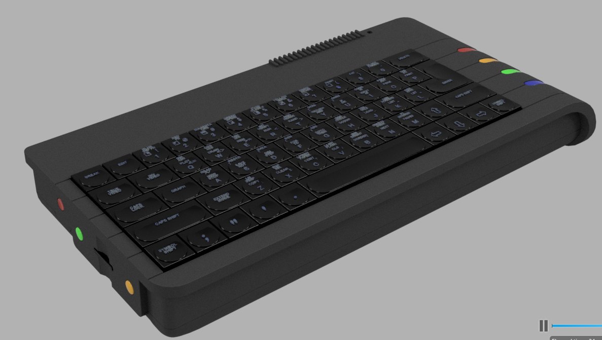
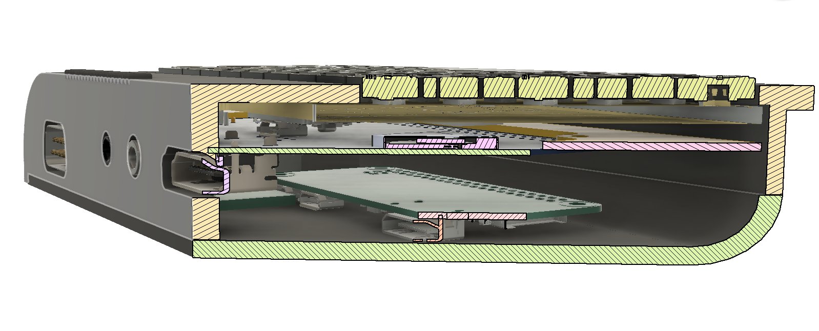
Another un-interrupted few hours of Laptop time and I’ve now gotten to the point where….All the stuff fits. Now it’s just small tweaks, printing and ‘production’ .
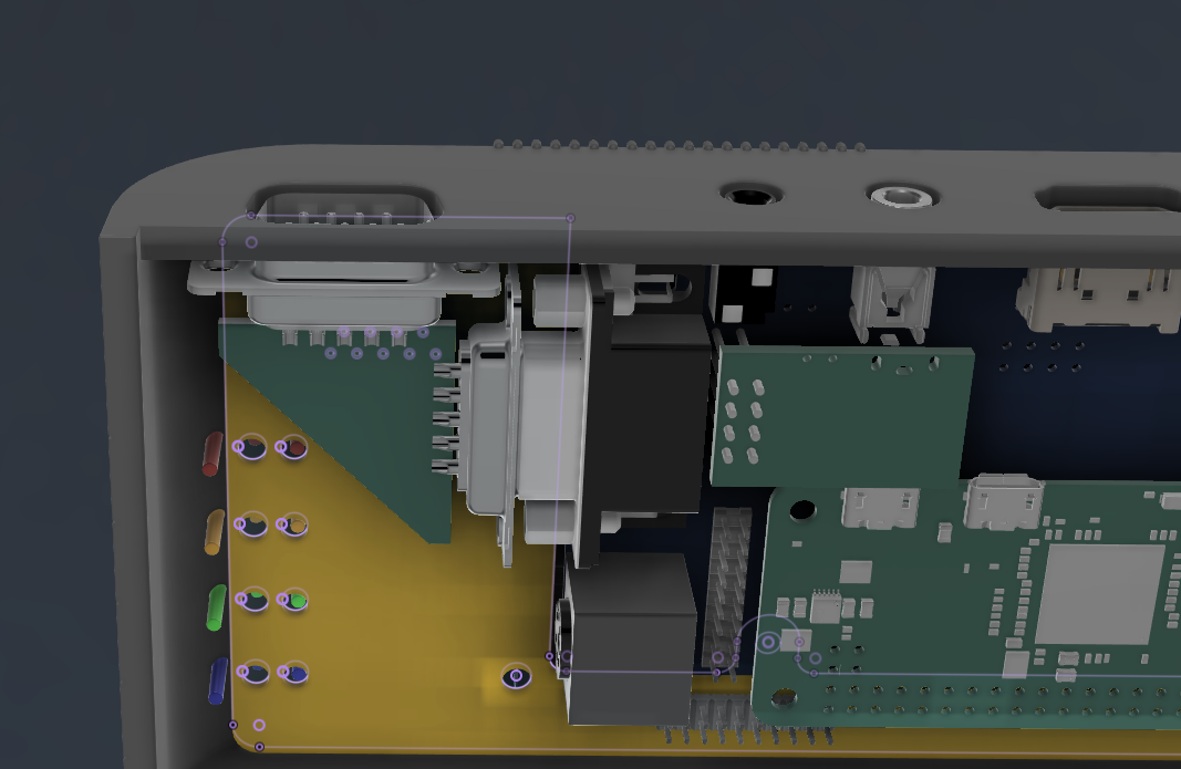
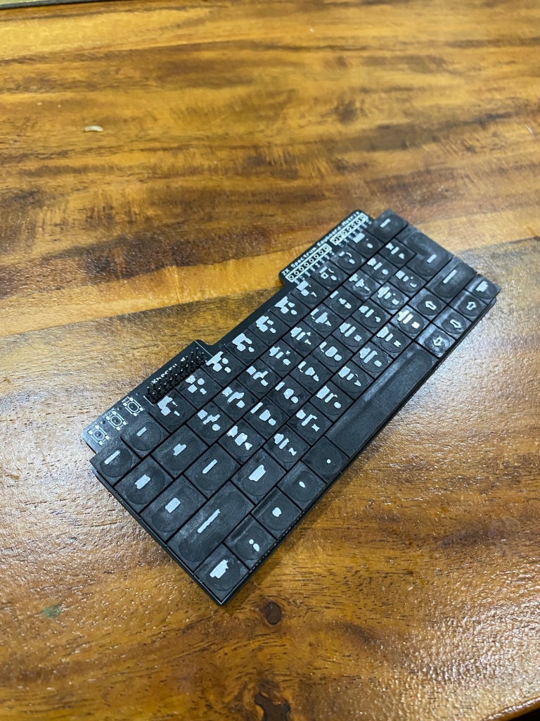
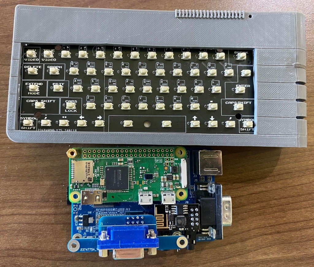
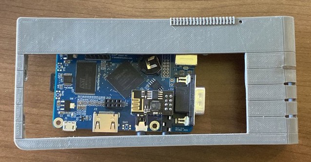
To get the PS/2 from the XBerry pi to the correct place on the rear of the case, I’ve put a small 6 pole ‘helper’ header over on the left.

I’ll then use just the small insert connector pins bit of the PS/2 connector and hand solder some wires for the first run. I might then make a fancy PCB for a final ‘final’ version
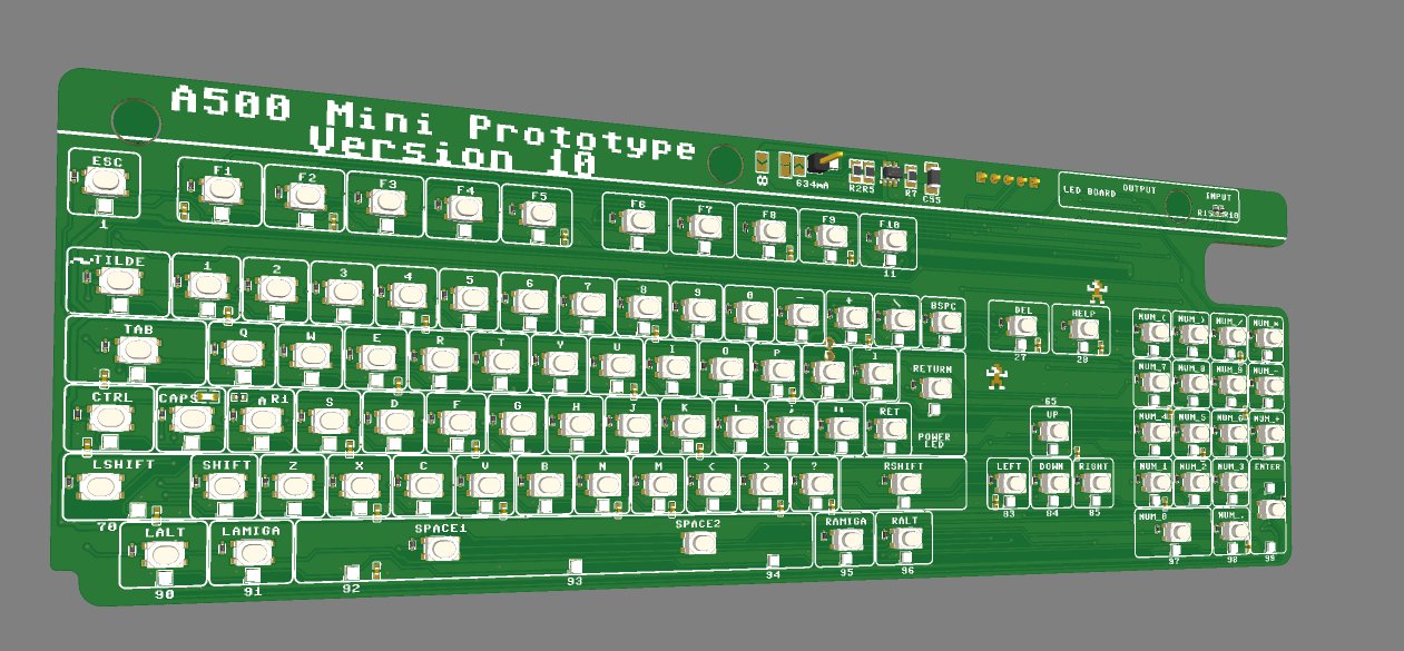
I’ve also now added a PS/2 port to the ‘rear’ of the keyboard PCB to save having a 4th custom PCB. For those that want ‘just a keyboard’ i’ll not be populating the rear side components (other than the Pi pico)
I’m now happy enough to pretty much freeze any problem solving, everything’s been solved now, so it’s down to relatively minor clearance and fitting tests now!
I’ll no doubt] need a few small revisions anyway and I’m really itching right now to make this thing Physical so soon, i’ll start using the 3D printers again, and be able to start back on the A500/ C64 and Blinkenator development!
For the Next Mini – some stats
Three Custom PCB’s seems to do the trick.
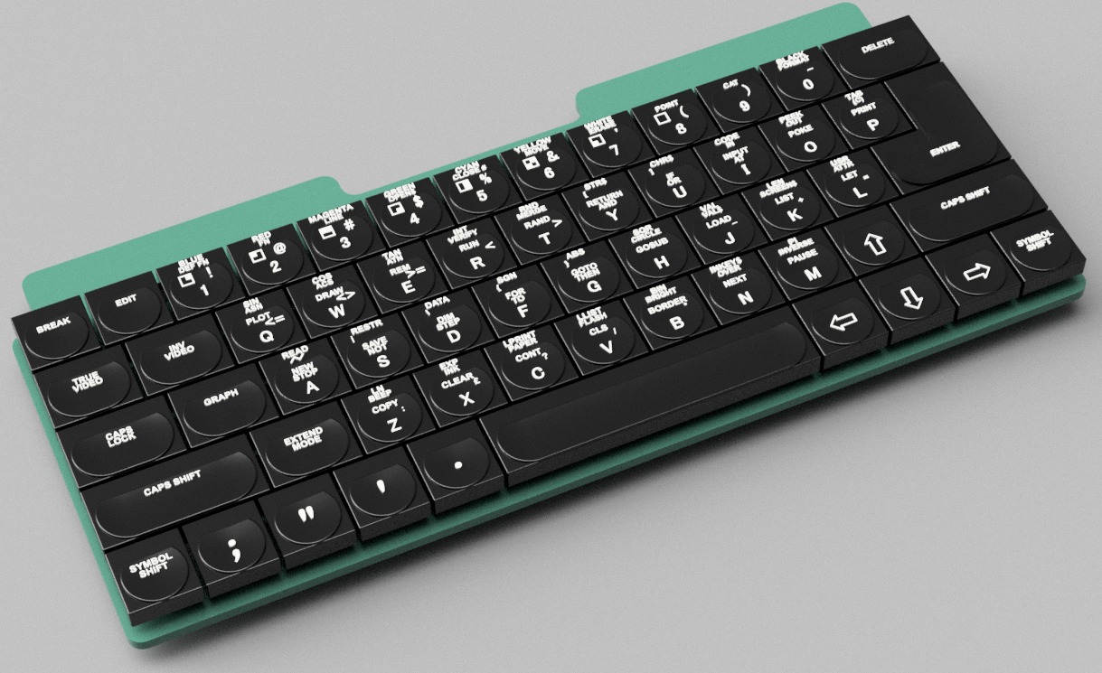
One Keyboard PCB (Duh!)
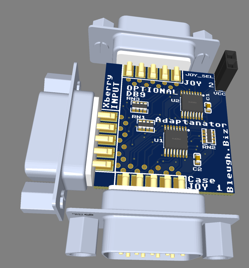
One Joystick Adaptor
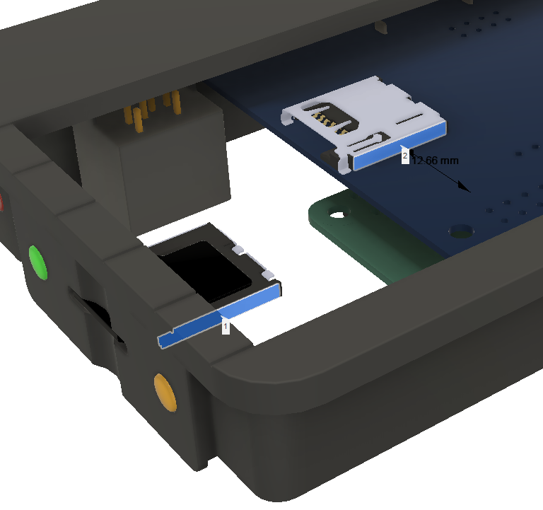
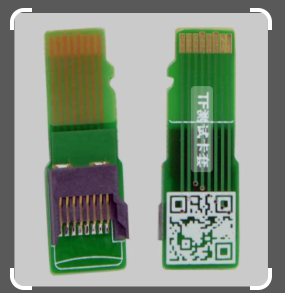
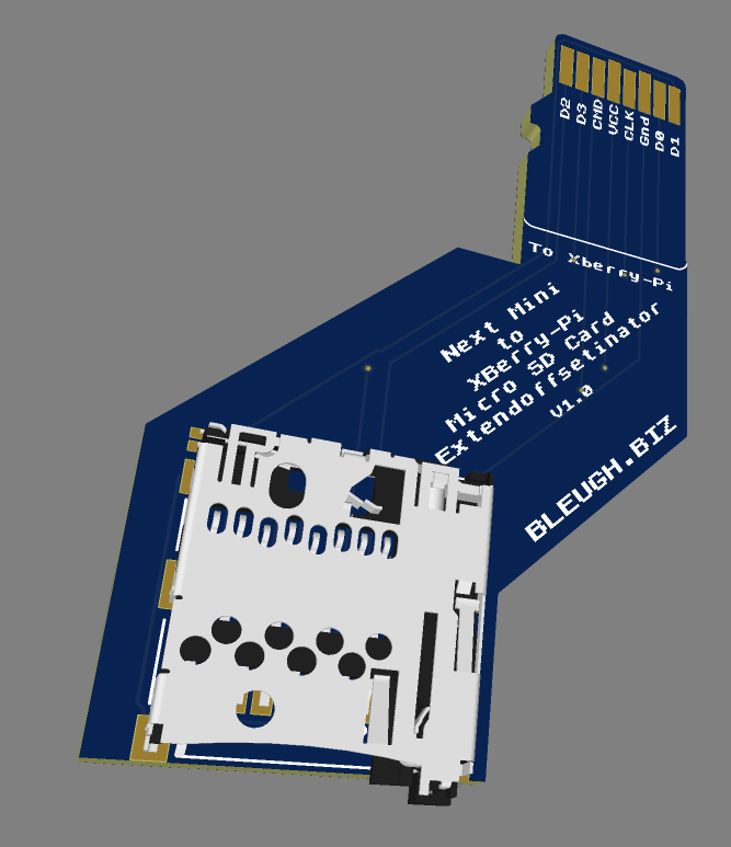
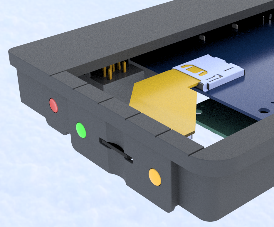
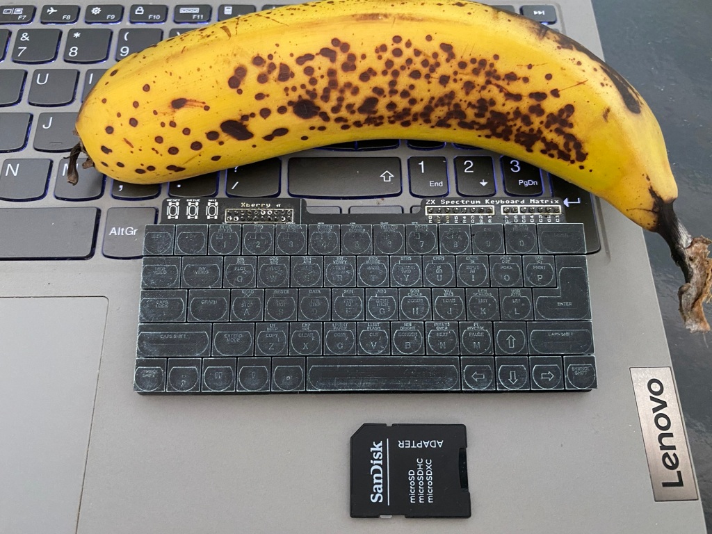
One SD Card Adaptor
One Pi Pico
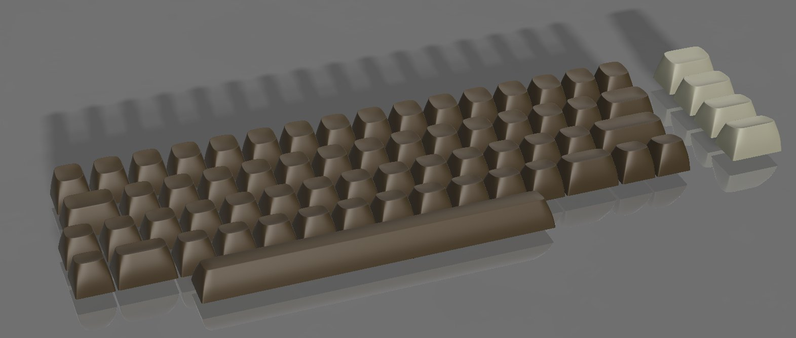
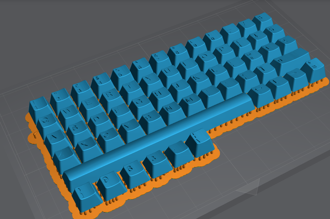
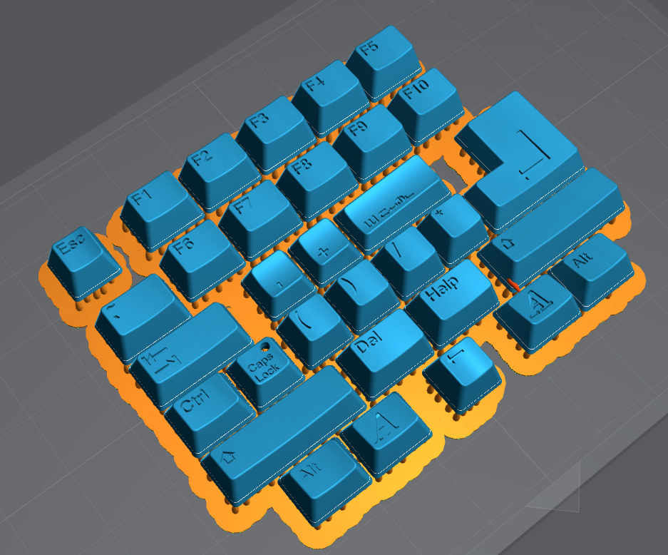
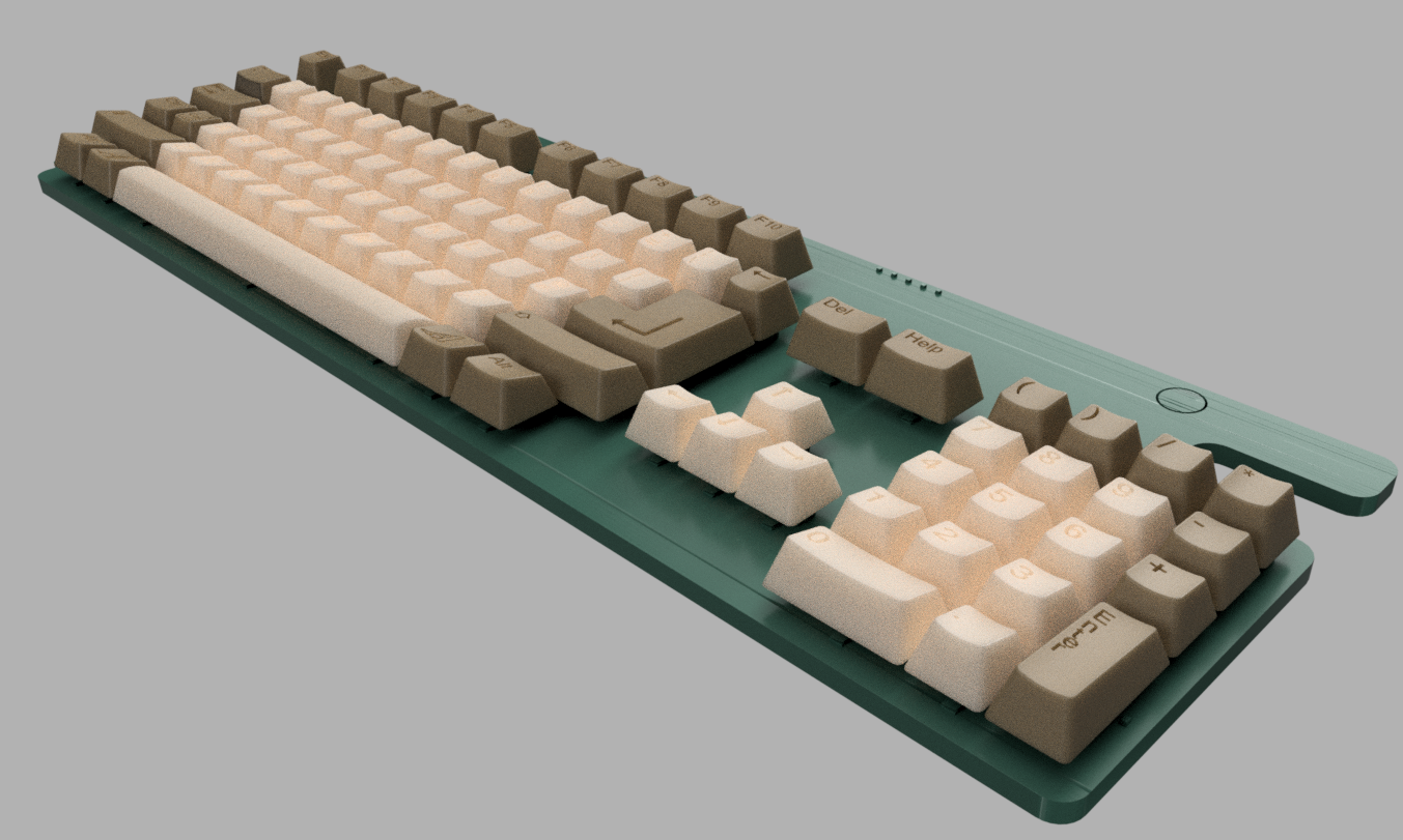
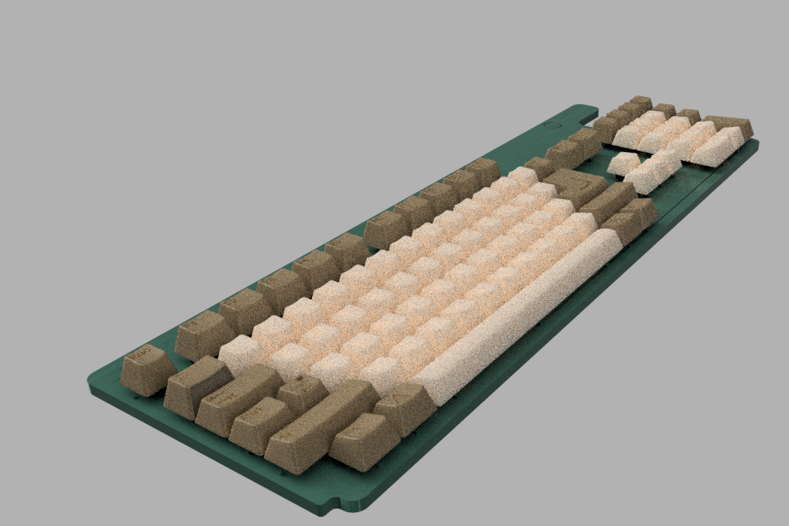
Nearly 70 3D printed parts in Six colours


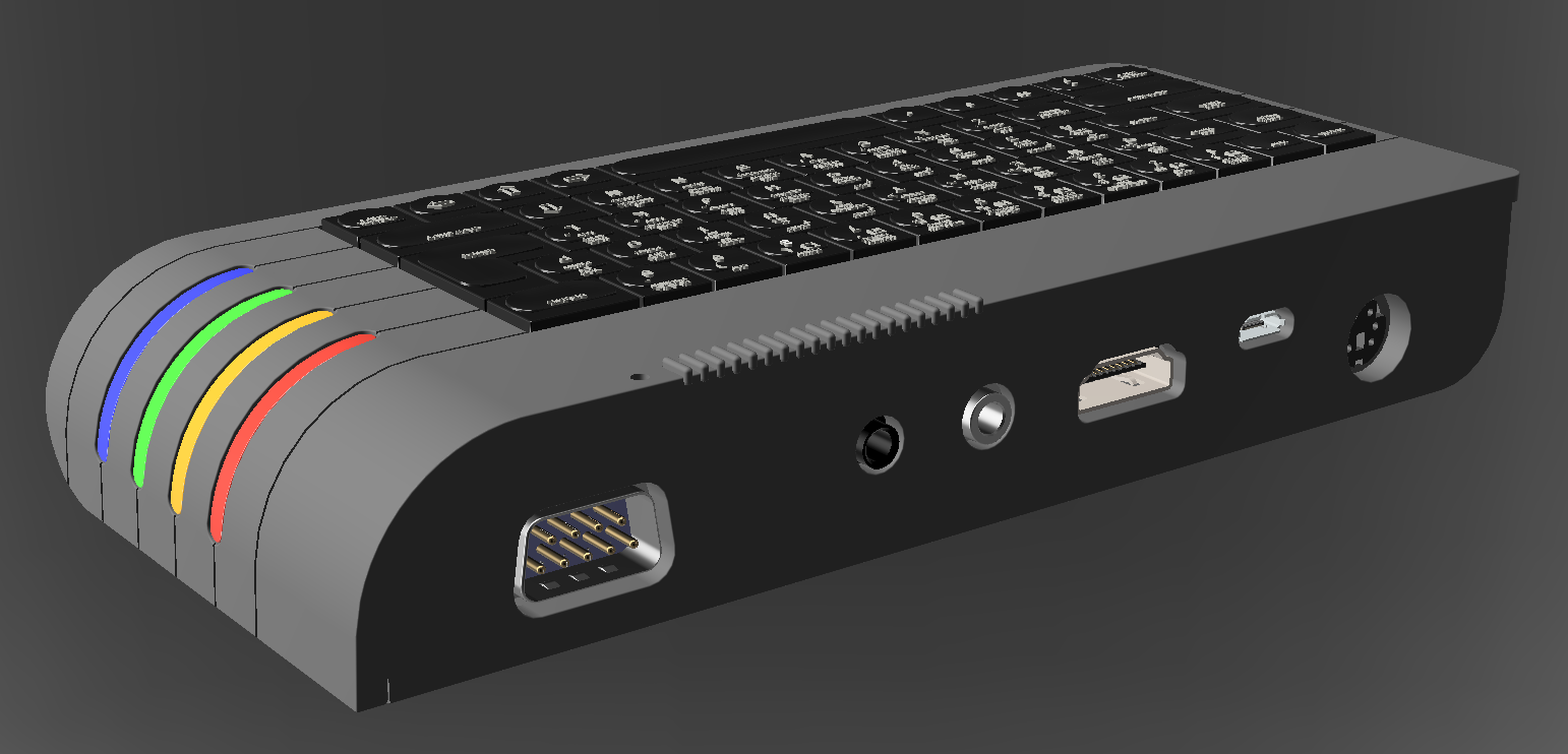
The two new PCB’s in Yellow – The ‘internal’ DB9 won’t be present on the Next Mini – it’s just there for a standalone product idea