
and i’m well chuffed to say – they’re almost alive!
There’s a few teething problems however,
My ‘excellent’ idea as can be seen on my last post – https://bleughbleugh.wordpress.com/2020/05/19/spectrum-next-light-strips-more-first-light/
to use some PCB grounding spring contacts to provide a quick fit connection didn’t really pan out – the contacts simply didn’t solder on easily, too difficult to align correctly and quite weak – I tore a few pads off trying to get them aligned and correctly ‘grippy’ on the insert.
multiply that by 16 each board – the first one took me about 2 hours to get to be in an ‘ok’ state – Not really acceptable for a mass production product – not that this’ll be mass production but I’d rather not spend half a day on each of these getting them ready for sale……..
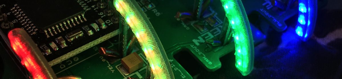
The second slight issue – See the photo below
The PCB is laid out on top the next board in the position it’ll be installed in.

There’s a prize for someone that spots the goof-up
Have a further look at the PCB powered up………..

Yeah, I got the inserts ‘back to front’ – That’s the result of working on a bottom mount PCB from the bottom…….
There’s two ways I can fix this
Simply rotate each LED by 180 degrees on the PCB and install a bodge wire to swap the input and outputs around………
OR….

I can simply re-design the LED insert and improve upon it!
a few reasons to re-design,
The first 6 LED version still has a bit of point brightness – I fear that even with the SLA printed inserts it won’t be diffuse enough..
Some statistics
8 LED’s – This should spread out the light more, reducing the hotspots a bit
0.4mm Slimmer – this lowers the LED’s further into the case, allowing much more plastic to sit above. I’m hoping this will de-focus the light more
Reversed connections to match the reversed controller board!. reversed is the new non-reversed now 🙂
New insert PCB’s are on order and should be here in a couple of weeks, I’ve bitten the bullet and ordered FIFTY….Also a few hundred more LED’s and a large tube of solderpaste.
Doing these first 10 dev boards is going to be fun – 320 1.5mm LED’s to be hand soldered!
The Controller board fits inside the case almost perfectly

I’ve slightly offset the J15 connector on my PCB to the one on the next. This offset gives a lot of friction, but needs some long term testing – the standard header I installed on one of my boards seems to work well as a friction fit. BUT, i’m not convinced that 32 LED’s, each pulling 5-20mA, (depending on which datasheet I refer to) – or between 160-800mA total depending on how I end up setting the brightness…..800mA is a LOT to pull
I’ve purchased a new gadget – A Riden RD6006 Benchtop ‘power supply’ so once i’m set up, i’ll charaterise the LED’s and current draw to set the software limits appropriatley
I doubt i’ll take nearly an amp on this board 😛
One further small mistake on the dev board –

When originally designing this controller board, I was to use a 3.3v Arduino to make it compatible with the Next’s 3v3 i2c.
For a few reasons, I’ve changed to using a 5V arduino and putting on-board a level translator device – this gives a 5V buffered i2c output that anyone can easily plug into
I forgot to change the net names….The board still ‘thinks’ the Arduino is either powered from RAW (it’s ‘unregulated input’) or 3V3 VCC…
The RAW input drops a few volts through a voltage regulator on the arduino to give the arduino a nice regulated 5V.
The next output is 5V….it’s not enough to power the Arduino through the RAW pin…
Took me quite a while – and a bit of soldering hackery to figure that one out as the speccy picked the board up perfectly when patch wired in place..
USB powered, it works perfectly
in the Next it doesnt….
The fix – I think I can just short the RAW pin to the unconnected VCC pin on this first batch –
and, finally

See that i2c device, found at address 0x45………..That’s the Blinkenlight 2000 PCB :-), alive and inside the Next!!!
